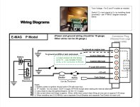
This is what I went with; and off-the-shelf solution from Steinair (note the wiring diagram included:
https://www.steinair.com/product/locking-toggle-switch-p-mag-test-on-on-mom/
Thanks for posting the diagram.
This switch is doing two separate things.
First it is enabling and disabling the P-Mag with contacts 2 and 3. The yellow wire is the "kill switch" wire connected to the P-Mag. when the switch is in the down position contacts 2 and 3 are connected, and the "kill switch" wire is grounded, disabling the P-Mag. when the switch is in the middle "run" position and the momentary up "test" position the switch is connecting contacts 1 and 2 leaving the kill switch open and the P-Mag capable of firing.
The other half of the switch is running the P-Mags internal alternator. The P-Mag has an internal alternator that needs ships power to energize, but once the engine is running it should keep itself running without an external power source. To test this you momentarily remove power from the P-Mag alternator and watch to make sure there is no RPM drop, indicating the internal alternator is working. In the "off" position and "run" position contacts 5 and 6 are connected providing 12v to the P-Mag. In the test position contacts 4 and 5 are making contact, removing power from the P-mag.
The switch is depicted upside down as it will need to be positioned this way for the spring loaded test position to be at the top.
A typical P-Mag check using this switch would look something like this:
with the engine running
1. Move the left ignition switch to the off position, observe the RPM drop.
2. Move the left ignition switch to the run position, the RPM should recover.
3. Move the right ignition switch to the off position, observe the RPM drop.
4. Move the right ignition switch to the run position, the RPM should recover.
5. Move the left ignition to the test position, RPM should remain stable. Release the switch and it should return to the run position.
6. Move the right ignition to the test position, RPM should remain stable. Release the switch and it should return to the run position
I hope this helps!