What's new
Van's Air Force

Don't miss anything! Register now for full access to the definitive RV support community.

Trim buttons on Control sticks not working

thiggins

Well Known Member
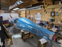
I'm in the process of attaching the empennage, and wanted to verify everything before final riveting. ( No wings attached )

In my shop, with everything powered up, good voltages...
I cannot get the trim buttons on the sticks to work.
From the Garmin side ( configuration menu ) all is good. I can do full up trim and full down trim via the Garmin menus. ( Strange thing also, the full up and full-down trim voltages seem reversed. I can fix that, but...)

Everything else seems to work great. This is the only issue I have right now with the electrics.

I've downloaded the latest everything, re-loaded everything ( config files, g3X updates...). I can hear the pitch servo click when changing indicated airspeed to true airspeed.

I've also been studying the wiring diagrams and wondering if it's an AV-60000 problem. I even tried disconnecting the pilot side stick, but not the co-pilot side yet.
*
Ideas?

Thanks in advance
 

Attachments

  • PXL_20231118_174535564.jpg
    PXL_20231118_174535564.jpg
    259.6 KB · Views: 71
Last edited:
Have you tried jumpering voltage directly to the trim servo just to confirm it’s working correctly? A 9-V battery is all you need. If you can jumper it at the DB9 connector at the AV-60000 it would confirm your connection at the servo too.
 
Have you tried jumpering voltage directly to the trim servo just to confirm it’s working correctly? A 9-V battery is all you need. If you can jumper it at the DB9 connector at the AV-60000 it would confirm your connection at the servo too.

“… From the Garmin side ( configuration menu ) all is good. I can do full up trim and full down trim via the Garmin menus.…”

Yes, trim motor works fine, I can test it from the Garmin configuration menu successfully.
 
Are your stick grips rated to carry the current required for the trim system? I know some of the Ray Allen grips need to be paired with relays because of that issue.
 
Just check the wires go to the correct pins on the 50 pin connector . We were tracking down a couple of problems and found the wires were in incorrect pin holes on the large connector . Four wires so far and I suspect we will find more with the latest problem we have. The circuit diagrams on the downloads page are available to help. I don’t think the checking on the supplied loom is all that good.
 
Trim

Just check the wires go to the correct pins on the 50 pin connector . We were tracking down a couple of problems and found the wires were in incorrect pin holes on the large connector . Four wires so far and I suspect we will find more with the latest problem we have. The circuit diagrams on the downloads page are available to help. I don’t think the checking on the supplied loom is all that good.

Yep. Start by checking the wires that operate trim. Make a jumper with the correct gender pins and jumper them a pair at a time. If the Garmin runs the trim, it has to be between the sticks and the final D-sub. If none work, my money is on an open ground wire.
 
Last edited:
Yep. Start by checking the wires that operate trim. Make a humper with the correct gender pins and jumper them a pair at a time. If the Garmin runs the trim, it has to be between the sticks and the final D-sub. If none work, my money is on an open ground wire.

All the other buttons on both sticks work, so ground there must be good.
Garmin drives the trim motor fine. 50 pin Dsub ? Very confident the 9 pin is good.
 
Wiring

All the other buttons on both sticks work, so ground there must be good.
Garmin drives the trim motor fine. 50 pin Dsub ? Very confident the 9 pin is good.

Easy to find out. Like I said. Short the correct pairs starting at the connector closest to the system and work outwards.
 
Easy to find out. Like I said. Short the correct pairs starting at the connector closest to the system and work outwards.

Thanks for the help.

I just checked the pins on everything with "trim" on it:
AV 50 pin and 9 pin, pitch servo, sticks, trim motor itself...
Nothing obvious, no wrong wire colors, nothing fell out.

I will try your plan and bridge the pins (trim up and down) to ground going into the AV-60000
 
Resolved!

After staring at the wiring diagrams for hours, something just didn't make sense.
I figured out I had failed to utilize the 9-pin connector already in the harness as provided by Stein. It had the 2 pins already populated that I was missing. I combined my pins with that connector, and everything now works.

I believe I can say that the harness Stein provided me was perfect, every pin.

:cool:
 
Back
Top