Make it easier
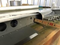
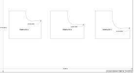
Rolling the edges with the templates was difficult enough.
Excuse the thread drift, but here's a tip. This isn't my idea, it came from someone else a long, long time ago.
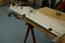
Buy two clean pieces of thin wall galvanized pipe, 1" internal diameter and 1.5" internal diameter. Mine are 26.5" long, I seem to recall the length mattered in terms of the rudder, and the outside diameters are 33mm and 42+ mm respectively. Get some cheap sockets of a size that "just" fits inside the pipe, two of each. I used 3/8" drive sockets. Drill 3 holes around the circumference at each end, and weld the sockets in place on each end. Grind off any excess and make sure the welds, and for that matter the entire pipes, are clean and smooth. Sand if necessary.
Carefully draw a straight line along the length of the pipe. Tape the rudder/elevator edge to be rolled to the pipe with duct or gorilla tape. With the edge to be rolled lying flat on a table, i.e. the roller is on top, use a 3/8" ratchet or breaker bar on each end to perform the roll, pressing the pipe "down" on the table at the same time you rotate it. With the ratchets/breaker bars each end you have a great deal of control over the rotation. I also used the same pipes single ended for those bends where you can't get to both ends.
The smaller pipe is for the elevators and top of the rudder, the larger pipe for the bottom of the rudder. I think.
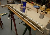
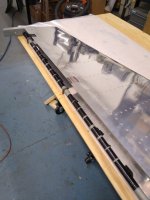
Excuse the rust and lousy welding on the following picture, don't know why I've kept these but this is what I used many years ago: