I had an RV-3B with pristine paint job that I successfully added the Duckworks leading edge bracket and lens assembly with a Baja Designs combo taxi/landing light. Since I only put one light in one wing I chose the Baja unit with two LED elements clear for landing, two with vertical fresnel dispersion for taxiing on the ground.
Here is a photo of the Duckworks metal bracket with the Baja Designs landing light assembly as described. The square adapter was made by a fellow RAF'r to specifically fit Baja units to the Duckworks bracket. After dealing with FlyLEDs and seeing their stuff I might would have gone that way instead as the Baja is heavy duty and well, very heavy:

When it came time to cut out the LE for the lens I was very nervous about ruining the paint. As a result I ended up installing the skin fasteners opposite positions than the Duckworks instructions. In other words I put the rivets on the bottom edge of the lens cut out and the screws on the top edge. I did not plan on any touch-up paint work so that was the primary reason for putting the screws on top. That would help keep any unwanted marks or paint damage created by the dimple dies and rivet squeeze on the bottom of the wing where they were less noticeable. Also, any damage on top created by the dimples for the screws would be hidden under the screws. In the end my concerns about paint damage were not as big a deal as I imagined and the final product looked great. The retrofit looks original.
More specific details on the cut-out process. What I did was lay out the cut out by center-punching the center of the radius of each the 4 corners of the cut out. I facilitated this by re-drawing the Duckworks template in CAD and printing it out on vellum paper with the corner radius centers marked with bullseye crosses.

I decided that rather than marking the cut-out with ink and cutting to the line to I would actually score the paint with a sharp scribe so the work done on the removed piece wouldn't cause any peeling or marring of the remaining edges of the cut out. This first step was effectively cutting the paint surface to the final line prior to any other action. I started by using a scribing compass to score the paint in a radius arc at each corner using the center punch marks mention above. Then I completed marking the sides of the cut-out by laying a flexible ruler making straight tangent lines between the 4 corner arcs both vertically around the leading edge and horizontally top an bottom. So this line scored into the paint was the edge of the final cut out.
I didn't trust myself to do the actual cutting so enlisted the help of a great friend, master craftsman and fellow RV builder/owner Dennis Flosi to do the actual deed. He is also a veterinarian and surgeon so he has a steady hand. He is know in our area as the "Fastest Nut Cutter in the West".
I applied green painters tape on the outside periphery of the score lines to protect the adjacent paint. Dennis then cut just inside the score line with a die grinder/cut off wheel (Dremel would work too). Then he finished by delicately filing up to the score line with mill files, sand paper and whatever else he deemed appropriate. I kept busy doing other things and tried not to bother Dennis while he was working but I felt like an expectant father in a hospital waiting room.
The final cut out was beyond my expectations and looked like it had been done during the original wing construction with absolutely no paint damage or marking. I was elated. The only slight hint that might be noticed by an extreme close up inspection was the edge of the cut out is not painted. But it is practically unnoticeable.
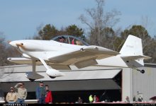
The dimples for the bottom rivets and top screws came out great, which I attribute using rivet tape prior to dimpling and also the original polyurethane paint which has some stretch. I wish I had a close up photo of the final product but didn't take any. And I sold the bird earlier this year so I don't have easy access. But here is a nice picture on the ramp showing the new landing light:
Jim


")

