What's new
Van's Air Force

Don't miss anything! Register now for full access to the definitive RV support community.

Is there really any interest in 3D CAD models of Lycomings?

Tall_Order

Well Known Member
Patron
Line up an experimental Lycoming 360 parallel valve, 360 angle valve, 390, 540 and hire a 3D scanning firm to spend a few hours to 3D scan them and generate a quality STEP file for each. Unobtanium^4 these days perhaps? :LOL:

Say with just a sump(horizontal vs vertical not a game changer?), crank case, cylinders, valve covers. No individual things like baffles or accessories. Just have 'em LIDAR the exteriors high resolution; no need for internal engine modelling. Now we can "CAD pick/evaluate" dimensions to make a scale model, or even send the file to a local shop to machine out of a foam block, etc. Perhaps individuals can even CAD trace the key dimensions make up a medium fidelity model like those wooden dinosaur skeletons, depending on individual needs and budgets to help with FWF fitting while waiting for the real deal...

Perhaps this is a chicken or the egg situation, but what is the best way forward and how much is a CAD file like this worth? $20, $50, $100, $150, more? How many of us really use CAD? Is this too niche? Who would have an example of each these engines at the same place at the same time and should money be pledged in advance for the project or should somebody just do it on their own initiative. Thoughts?

(To Admin: feel free to turn this into a poll; I couldn't find an option for this feature)
 
3d modles of engines has potential. Fact is builders want to build and having an engine to fit stuff up holds them back. Since the backlog is so long these days we have a problem that did not exist 4 years ago.

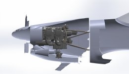
If I'm building the cowl and my engine isn't in the shop then I must be able to bolt a flywheel to the model to establish a exact know location of the spinner. that means the model must have the crank flange on it.

RE: accessories, If we can bolt the Carb or FI servo then I can fabricate the lower cowl for the intake and airbox. I can also fabricate the engine control cables and position the oil cooler. If the cowl is going to be tight then I'd want the exhaust to be able to bolt up to it as well. I think 3d modeling can duplicate these attach points. Could you model an oil pan to accomodate both a vertical and horizontal induction mounting pad?

Then I suppose one can go into business and rent these foam or plastic mock engines to builders.
 
So the really important things to fix in 3D space are the flywheel flange and the carb/servo inlet flange. The cowl will clear the rest of the engine features without effort on the builder's part.

Questions that come to mind when considering a plug made of anything besides an engine and crankshaft core:

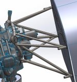
How uniform are the engine mounts in our kits (if sufficiently so, the firewall could be used as the reference plane rather than the elastomer mount cups on the mount)?

If bolting a lightweight engine plug to the mount, either using or accounting for the Lord mounts in the construction of the plug, how do we accommodate the sag that inevitably results when the elastomers are loaded with the engine weight? Seems like failure to do this would throw the spinner to cowl alignment way off.

Just some under-caffeinated thoughts from a geriatric spectator a few days status/post general anesthetic and kidney stone destruction who's trippin' on Toradol and wishing he were back in the saddle already. Sucks to be on the other side of the white coat for once - but humbling.
 
For building(assembling) a RV I see no real use for 3D Lycoming engine files. But if you're designing a complete firewall forward including the cowl for a 'build from plans' it's very useful. I found a 3D model of an O320 and used it for my design. Later on I found a free download of the IO360 https://grabcad.com/library/lycoming-io390-210-hp-1

I do frequent 3D scanning and Reverse engineering. The scan is only a few hours, but the work to get a useful 3D file takes many hours and makes it expensive.
 

Attachments

  • Motormount_CP1320-1.JPG
    Motormount_CP1320-1.JPG
    48.1 KB · Views: 33
  • James-cowling-compare-2.JPG
    James-cowling-compare-2.JPG
    123.1 KB · Views: 33
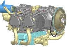
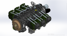
It's already been done. I bought the models from Aero Maceio several years ago
Just bought the 360 with the name AEIO-360 (I thought A meant "angle", but "CAD slicing" a section view it is undoubtedly a parallel valve. Obviously some more to learn here for me... But lucked out as that's the engine I'm planning for the '8A

I can't imagine how long it would have taken to generate these; the fidelity of these CAD models is INCREDIBLE!!! 😎

Even better if there were still room for a bit of oil.

Dave
Well that would just be lost in the "beat to meet, file to fit" part tolerances when I try make a mockup on my DIY CNC 😜
 
Just bought the 360 with the name AEIO-360 (I thought A meant "angle", but "CAD slicing" a section view it is undoubtedly a parallel valve.
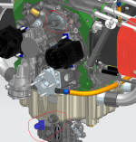
The AE is aerobatic, as in provision for inverted oiling system from the factory. From the Operator's Manual: "Although similar to the Lycoming IO-320, -360 and -540 engines, the AEIO aerobatic series differ in respect to the sump and the inverted oil system". See red circled parts below specific to the AE config.

1710130960699.png
 
Back
Top