What's new
Van's Air Force

Don't miss anything! Register now for full access to the definitive RV support community.

Instrument Panel - Symmetric Vs. Asymmetric - RV-7 Slider

gmcjetpilot

Well Known Member
What is your opinion specifically about Symmetry..... I know it comes down to choice, preference, compromise. What do you think of these three...Sometimes it is stand back, close one eye and hold thumb up and say looks good or good enough. My thoughts

Top - symmetric (to center bolt) has access cover is same size as EFIS so a second screen could be added. I am not likely to add a second screen however.

Middle - semi symmetric as a less crammed in to the left, but still good access to the center stack.

Bottom - Asymmetric and more room to add another gauge. ( I already own, the Davtron M811b timer and the G-meter, both handy)

I am leaning to the middle one because it looks nice, Also if I want to add gauges like the clock/flight/timer or G-meter they can go in the access cover. They require little to no wiring.

What is your experience, suggestions, cautions, regrets about symmetry. (Note: majority of the equip is locked down, bought, test wired ready to mount. Location of switches, power jacks, dimmer, intercom still in flux, and I own a box of circuit breakers so those are also firm.)

.

panel design7b.jpg
 
I vote for Symmetric. I considered an asymmetric layout but my brother (Walt) convinced me to go symmetric and I am glad I did - it just looks more balanced. (Research as shown that people with very symmetric faces are more attractiv).

I have dual G3x’s with a GTN 750, GMC 305 and a garmin audio panel in the center. I have a G5 on the far left side & CBs on the far right side.
 
I think “balance” is a better word than symmetry. You can have an asymmetric panel as long as it is balanced in visual “weight”.
Keep in mind, you can see and reach everything easily across the panel in a 7.
Here’s mine. It’s not symmetrical but has pretty good balance. It gets harder with the big screens when you don’t put two of them in, but it’s still doable.
There are endless discussions about placement of things in a panel. Some are just fine with keeping the focus in front of them. I for one don’t like a bunch of blank panel space on one side, which is hard to avoid if you have to have a “map box”.
IMG_8929.jpeg
 
The center rib sloped down as it moves forward so one thing to consider is how deep is that EIS box? If more than a couple of inches you can save yourslf from having to cut into the center panel by either going with #3 or maybe dropping the entire center stack lower.
 
I don’t like the bottom one because the gps is too far from your line of sight to the attitude indicator.
I’d also put the EIS at the bottom. You’ll never need to look at it. However, as suggested above, maybe high is needed to avoid re-engineering the support rib behind the panel?
 
Layout #1 center rib likely interferes with GTN 650. Layout #2 center rib may interfere with GTN 650. Layout #3 GTN likely misses center rib, but right edge will be close to outside rib. In all cases, do not underestimate the room required to interconnect and wire the components. In all cases, the subpanel will have to be cut, at least for the GTN 650. I ended up cutting a huge hole out of the subpanel from the LH outside rib to the RH outside rib. But then, I had to reinforce the sides of the subpanel with 3/4 x 3/4 x 1/16 angle and add a 1" x 1" square aluminum crossmember to tie the subpanels back together.I did not have to cut any of the ribs as my radio stack was similar to your Layout #3. Do not underestimate cramming all this stuff (esp radio stack) between the ribs and the subpanel.
 
Function more important than symmetry. Symmetry only overlaps function if the airplane is flown equally from the right and left side.
I do like the term balanced mentioned by JonJay
 
I think “balance” is a better word than symmetry. You can have an asymmetric panel as long as it is balanced in visual “weight”.
Keep in mind, you can see and reach everything easily across the panel in a 7.
I for one don’t like a bunch of blank panel space on one side, which is hard to avoid if you have to have a “map box”.
Nice looking panel. Good points. I have a map box but likely not going to use it. I understand the blank panel look, but It does not bother me. I am kind of committed to having access behind the panel w/o going inverted submariner. I was cut big openings and then go over it with secondary removable panels over instrument panel, but it adds weight, cost and complexity. I don't think it is needed. The GRT EFIS will come out and leave a big hole on pilot side. The access panel will give me access to "systems". Again I could put some instruments (G-meter, clock, or map box. I have a Van's map box but likely not going to use it. It is a too deep and would penetrant the mid bulkhead. However I could shorten it and have it come out with the service panel? It would not be for heavy items. Who uses maps anymore? But it would just barely hold my iPad Mini !!! Hey.
The center rib sloped down as it moves forward so one thing to consider is how deep is that EIS box? If more than a couple of inches you can save yourslf from having to cut into the center panel by either going with #3 or maybe dropping the entire center stack lower.
YEP the EIS is a tad over 2" deep. It is as high as I can get it without hitting the rib. The rib flange is about 1.9" and add another 0.3". Cutout is about 2.2" from top edge of panel (2.1" from top of bezel).

I don’t like the bottom one because the gps is too far from your line of sight to the attitude indicator.
I’d also put the EIS at the bottom. You’ll never need to look at it. However, as suggested above, maybe high is needed to avoid re-engineering the support rib behind the panel?
YEP I really want EIS on bottom, but as Desert Rat....the rib is in the way. The EIS is shallow so it went to top. The ICOM is a full 10" deep. As far as modifying the Rib/Stiffener. I thought about it. Once you Mod one thing it starts to change others. This is support for roll bar/windscreen frame. It can be done. This is why Asymmetric has some advantage. It allows deep "stack" avionics to be moved higher as shown here with no modifications.
panel design7d.jpg

(Note: For those who don't know those 3 screw holes that are off set along top, are securing panel to structure. The ribs get deeper as they go forward... 1.9" at panel & 7" deep at firewall. To clear typical deep avionics 3.5" down offset from top may be needed.)
 
Last edited:
I would check the Navigator installation manual. I dont think the bottom one meets the requirements, but I could be wrong. When I laid out my panel, there was a requirement for viewing angle to the pilot.

Also, Imwould avoid using a keyed ignition switch. I think toggles for the mags and a keyed starter switch is the way to go. The keyed ignition switch is a single point failure. Mine failed ( in the air) during phase 1 at 10:hours.
 
I would check the Navigator installation manual. I don't think the bottom one meets the requirements, but I could be wrong. When I laid out my panel, there was a requirement for viewing angle to the pilot.

Also, Imwould avoid using a keyed ignition switch. I think toggles for the mags and a keyed starter switch is the way to go. The keyed ignition switch is a single point failure. Mine failed ( in the air) during phase 1 at 10:hours.

I don't disagree. A good new Bendix key switch Off R L Both Start are $500. PMA'ed they $615. I have Mil-Spec Locking toggle switches planned. I just showed it to see what it might look like. It is handy doing the work of three switches, two mags (P-Mags) and start. Also it adds some security. Still working on the ignition/start switchology and security.

As far as the GPS175 viewing angle, good point. There is a thread on VAF which has good info.
https://vansairforce.net/threads/field-of-view-angle-requirements-for-garmin-navigators.207537/

I don't think it is an issue but a consideration. The viewing angle is within limits of the screen it self, but there are human factors. The Canadian Policy Letter (PL) on this subject (link in thread above) indicates recommended center of AI to Navigator be about 13" apart. Coincidently my bottom sketch has center of EFIS to GPS is 13 inches apart. FAR Part 23.1311 & 1321, addresses location of instrument topic as well. However USA built EAB's are not controlled by Part 23 or Canada. Still wise to look at all this information. Thanks for the tip.
 
Last edited:
Definitely symmetric. That's just who I am. I'm an accountant and work is all about the debits equalling the credits, or literally, the left equalling the right. It flows over into other parts of life: every Lego assembly is always symmetric, right down to the color of the bricks. And so goes this in-process panel...
Symmetry Rules.png
 
#2 and put the navigator on top.
I dont think the navigator can go on top due to its depth into the panel. It makes a difference if you want to leave room on the bottom for switched.
Also, if I remember correctly, the comm radio is even longer than the navigator.
I, like so many others, had to trim the upper ribs and add angle stiffeners trying to get the stuff as high as possible.
 
I would consider not putting the EIS in the panel at all. Once you get it setup properly you can forget about it. You set the warnings and parameters in the EFIS.
i’ve been flying my 8 in it’s current configuration for 12 years and rarely if ever even look at the EIS which is mounted on the right side subpanel under the switch panel.
Just a thought to save space and clean up your panel.
 
One more thing: I put my ELT button on the left side so my passenger wouldn’t pull a Sponge Bob, get bored, and decide to push it.
 
Okay, if you want the EIS in the center stack, avoiding having to cut into that center rib is plenty of reason to put it up top. I'd question if it even needs to be in the center stack at all, because it seems like that space would be better served by being reserved for a future autopilot controller (which is also only a couple of inches deep) But if thats not in the cards, then I'd go with some version of option 1.

Just so you know, I also did my initial panel layout in that hangar flying program. It was really a great place to start, but I did have to/get to tweak some things that either weren't dimensioned correctly or had other stuff in the way.

One thing that stands out to me in all of your options is how far apart all of your switches and breakers are. You may want some spacing on your switches for ergonomic or operational reasons, i.e. don't put the avionics master next to the landing lights or whatever, but you can pack those breakers tighter than they appear to be and reserve space that you may need for something else in the future.

In my plane, I crammed everything under the sun into the panel, so space was at a premium. My toggle switch groupings are 15/16" center-to- center, And my breakers are center-to-center spacing of 0.7" and a vertical spacing of around 1.5". I was able to cram in 29 breakers and an ELT switch to the right of the symmetrically placed MFD...


Edit- I forgot to mention, I wouldn't be installing a davtron or g meter or any other stand alone just because I happened to have it on the shelf. If you want it just because you like it, thats one thing, but your PFD already has all that stuff included. How many clocks a G meters does a guy actually need?
 
Start with requirements and preferences, move to solution, cut the holes.

Looks are great, craning your neck to see something every moment important or reach a well used switch will make you hate the experience ...
 
Definitely symmetric. That's just who I am. I'm an accountant and work is all about the debits equalling the credits, or literally, the left equalling the right. It flows over into other parts of life: every Lego assembly is always symmetric, right down to the color of the bricks. And so goes this in-process panel...
View attachment 58476
Is there something wrong with this graphic? The instrument holes are symmetric to the panel, but the rivet/mounting holes across the top aren't symmetric somehow, because the center hole isn't centered on the gap between the two top center instruments. It looks like the spacing on the three holes right of center is smaller than the three holes left of center?
 
Personal preference would be #1. Symmetry. I know you don't plan for a second screen right now, but at least it'll be an easy option down the road. In the meantime, your passenger can velcro their iPad there for an in-flight movie, you can have a large glove compartment/lunchbox that won't spill things when you hit turbulence, etc. Having the instruments "tight" together on the left won't even be noticable.

I'm pretty sure that the Symmetric layout also places the EFIS dead center in front of the pilot... Relaxing it to the right a bit means your head always has to turn a few degrees to look at the screen. A small thing in VFR, but maybe larger in IFR?
 
I don't think it is an issue but a consideration. The viewing angle is within limits of the screen it self, but there are human factors. The Canadian Policy Letter (PL) on this subject (link in thread above) indicates recommended center of AI to Navigator be about 13" apart. Coincidently my bottom sketch has center of EFIS to GPS is 13 inches apart. FAR Part 23.1311 & 1321, addresses location of instrument topic as well. However USA built EAB's are not controlled by Part 23 or Canada. Still wise to look at all this information. Thanks for the tip.
You’re correct, part 23 doesn’t apply. But, for IFR, your OpLimits say you must conform to 91.205. And that refers to ‘approved’ gps. FAR 1 (definitions) says a TSO is one way, but not necessarily the only way, to have an approved RNAV system. Unfortunately, I know of no instance where faa approval has been granted, other than by TSO. The TSO also incorporates, by reference, the approved gps installation manual. And that is where you’ll find the placement limitations, a diagram with dimensions relative to the attitude indicator. It also has an important exception: if your efis can and does display all of the annunciations from your gps, then you may place the gps wherever you like. BTW, it’s my observation that DAR’s pay no attention to this requirement.
 
Paper doll all three to scale. Put them in different locations where you’ll see one, but not the other 2. After a predetermined observation period, pick the one that speaks to you most. If during your observation you decide to make pros and cons lists, this data could be used to quantitatively balance your qualitative ‘gut feel’. Good luck.

(I like #3 best at first glance.)
 
You’re correct, part 23 doesn’t apply. But, for IFR, your OpLimits say you must conform to 91.205. And that refers to ‘approved’ gps. FAR 1 (definitions) says a TSO is one way, but not necessarily the only way, to have an approved RNAV system. Unfortunately, I know of no instance where faa approval has been granted, other than by TSO. The TSO also incorporates, by reference, the approved gps installation manual. And that is where you’ll find the placement limitations, a diagram with dimensions relative to the attitude indicator. It also has an important exception: if your efis can and does display all of the annunciations from your gps, then you may place the gps wherever you like. BTW, it’s my observation that DAR’s pay no attention to this requirement.

All true. This is a rabbit hole. First no GPS needed for IFR (but practically speaking you need it).

TSO's and AML STC's in experimental kit planes (EAB) is not totally black and white or even applicable. When you install a TSO'ed GPS in an experimental, do you need to comply with the TSO like you do when it is installed in a Part 23 plane per STC? STC's don't apply to EAB's. Garmin GPS175 is approved under a AML STC to be installed in part 23 planes. The STC is blanket and not to specific airframes so it can be vague or generic.

Ran into this with a Garmin G5 in a certified Part 23 plane and how to set level pitch Ref. Long story, but following the G5's generic vague installation per AML STC (non airframe specific) by the mechanic, it resulted in poor calibration. It was fine if you like always being 4 degrees nose up attitude all the time. He followed the manual, set the airplane in a rigging attitude, not level flight attitude. Rigging is level to hanger floor. THINK about it, when you have a Vac AI and set level on the ground the plane is in a flying attitude approximately, nose up attitude. Cessna on gear tend to sit nose up which is near the attitude in level cruise flight. Please no need to point out in cruise level pitch will very with AC Wt. density altitude, power, etc. We know, but it is pretty narrow range, and indication of almost 4 Deg nose up for level flight is annoying. Back to the G5 installation. Again not specific to airplane, but says airframe manufacture manual. Cessna did not anticipate airplane in rigging attitude, level to ground to be for EFIS calibration 50 yrs ago. This results in nominal level flight, cruise, pitch indicating 3.5 degree nose up. That is fine, you can deal with it but not ideal. If flying a traditional Vac AI you would reach up and set it level, at least I would. With glass, TSO'ed PFD's and EFIS you can NOT have pilot adjustable pitch reference. No PITCH REF ADJUSTMENT FOR YOU! Maintenance can adjust it but strictly per TSO/STC. This goes back to early glass in Military and Airline late 80's. It applies to GA planes with TSO glass today. So do GA pilots have to accept nose up indication when level? No, at least not in my case.....

I found in the AML STC approved TSO installation manual a sentence about adjusting pitch Ref to account for aerodynamics . This allowed it to be calibrated to read more or less level in cruise not +3.5 degrees nose up. I ran this through Garmin and the A&P / AI. The AI adjusted per my input during annual. All is good. I learned a lot. Keep in mind this was a Part 23 airplane. Garmin makes a "experimental" G5 (not TSO'ed) which DOES allows pilot to adjust pitch reference in flight from the basic menu. The G5 for certified planes does not allow pilot adjustment (at least easily, it is highly discouraged). Technically if not an A&P you shall not adjust it (although if you know how to get into settings on the ground you can). It is not pilot adjustable period. If these STC were type specific and not AML the instructions to install them would be better. My point is the manuals are not always comprehensive.

What about EAB's? STC's don't apply. Regardless of legality, say not applicable to EAB, is it wise to follow the instructions as if you are Part 23?

To my shock you do NOT need backup or redundancy in your glass cockpit RV, no flight or Nav instruments or systems (electrical) redundancy to fly IFR in an EAB. Why? Because that is under STC's. In old steam gauge days you had Vacuum and one Electric T&B or TC, with pitot static instrument. The back up was it was dirt simple mechanical and you had vacuum gauges and one electric T&B, plus pitot static inst. Like magnetos they just work and assumed not to fail or the redundancy is built in. Now we have electrically dependent airplanes with three batteries, two alternators and a wind turbine. I am kidding but my point is EAB airplane with one alternator, one battery, and one AHAR "gyro", no back up, is good to go IFR. Legal but not a great idea.

Now we have EFIS with all Eggs in One Basket. My one EFIS does everything, displays ALL info, controls everything. It goes down I am screwed in IFR IMC with no back up. I however have backup of engine instruments, COM (separate control head), GPS (separate RAIM GPS) and 2nd AHAR with a redundant independent EFIS (with AS, ALT, AI, NAV), 2nd battery bus to run critical electrical items as well. All that is NOT in the FAR's for EAB's. You can fly with one PFD/EFIS, one AHAR, one Electrical system, one EFIS controlling and displaying everything in an EAB and no back up electrical. A Part 23 can NOT do that. They have to have backup. You can be legal and unsafe.

My EFIS is not TSO'ed or STC'ed. My point EAB's have different compliance requirements. We have a lot of leeway.

Related note TSO'ed ELT's are required to do certain flights. These TSO'ed ELT's have very specific antenna installation requirements. Many builders deviate to hide the antenna in cockpit, tail fairing, wing tip, for looks or reduce drag. Is that OK in an EAB? We don't do STC's in EAB's.... However like the TSO'ed GPS the TSO'ed ELT has installation instructions? Can we deviate? A TSO'ed GPS likely tells you put antenna on top of fuselage. Builders bury GPS antennas in all kind of places not spelled out in installation instructions.

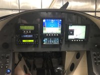
What is the answer. Does it REALLY matter where I place my GPS175 in the panel. Yes it does but not due to TSO or STC or FAR in my opinion. As a pilot you don't want to have to turn your head or lean over too much, to adjust the GPS in the clouds, to avoid spatial disorientation. However 30 yrs ago I did SINGLE pilot SINGLE engine IFR with no autopilot. I now think that can be more marginal than where the GPS lives in the panel. I still hand fly IMC, but don't have to, will avoid it single pilot if weather is low IFR. My RV has two AP servos. Not because I can't Scan, Cross Check, Interpret and Control, just that it adds safety and we have better technology. So if mounting the GPS175 to the left 3.25" closer to my hand makes it safer great. However GPS is ARINC 429 connected to the EFIS and backup PDF (showing a G5 but likely will be GRT MINI). The waypoints and CDI/VNAV are right in front of me. Plus I have autopilot. Really proficiency with the BOXES is more important, button-ology and knob twisting skills.

I am an active CFI-II again (took a few decades off for airline flying). I am use to flying from the the right seat, looking at instruments across the cockpit. I have two Inst students now. Fortunately they can fly and don't scare me (too much ha ha). I still demo a hand flown approaches from time to time in actual. These planes have G5's mixed with steam gauges. One has a old analog autopilot (I don't like) and the other no autopilot. I have them hand fly the IAP most of the time in the one plane with Autopilot. The difference between and old S-TEC and new digital autopilots in GA is night and day. Not a fan of equip dependence vs airmanship, but nice to have. However the ability to couple the approach and monitor like the big boys is nice. Now we need auto throttles?

For now we have to please the Designee or FAA when they do our approval inspection. What they write in the log book is key. When you get your limitations, it say something like Approved for Day/Night and VFR/IFR if equipped. You are the manufacture, so you decide if it is equip. it really is pretty vague how experimental planes comply without having Part 23 specifics. We don't have to comply with AD's or STC's because legally they don't apply to EAB's. That is subject to some interpterion and debate, but that is my story and sticking to it.... There may be exceptions or I am wrong. My position is be safe and reasonable, and comply with the FAR's always. Where the FAR's are not spelled out in regards to an EAB use good judgment.

For IFR, after the Part 91 list of systems, flight instruments needed, required airframe inspections, and Part 61 pilot qualification and currency, when it comes to NAV it says whatever you need for the flight? OK one VOR? Well in old days I did fly IFR with just a VOR. It was a 30 mile commute, knew the weather and alternate was drive to work. Not anymore. IAP's with VOR on the field are all but gone. RNAV and for the good is here but GPS need only apply. I have no DME, VOR. LOC, GS, MB, ADF, INS.... (Inertial Nav Sys want one ha ha). I just plan on the one TSO'ed GPS, that is it. Well not really the GRT EFIS has RAIM GPS (WAAS) and database, but that is another story, it is not TSO'ed. I do have a handheld Yaesu with VOR/LOC. If it got down to that to save me, it's a bad day. If you are a super serious IFR mission pilot, get VOR ILS DME,,,, and two COMS... DME is needed more than ever without GPS, due to markers and NDB's going or gone.
 
Last edited:
I have a lot of the equipment that you have and it is installed in a tip up RV6.
(This is the fourth panel iteration for this plane.)

It has the 10.1 far left with two Minis to the right of it. To the far right is an EX. The EIS is "hidden". It is NOT needed in view as you can set things up using the EFIS.

The current project (RV6A slider) is being built "FULLY SYMMETRIC". Big screen (10.1) in front of pilot, with a Mini to the outside (left) of it. Big screen (10.1) in front of copilot, with a Mini to the outside (right) of it. Those are all GRT. The center stack is all Garmin (GMA 345, GTX 375, GTR200 (x2)).

In order to get it to fit in the "fully symmetric" mode, you need for the "mini" to be to the outside.
The have the radio stack in the direct center, you will need to "adjust and then strengthen" the top center rib. You will also need to do a cutout in the bulkhead for the radios and cable to stick through.

I have a lot of time on the installed (RV6 tip up) setup. I was going to do a different setup (3x EX's) but I decided to make the panel in front of me look like what I have in the RV8. Having the Mini right there is VERY convenient for a lot of things.

The "new project" (symmetric) is chosen for functionality and beauty. What I will lose is reaching up with my right hand to use the Mini. What I will gain is a LARGE map to the right if I am flying alone. Also, I gain full functionality for the person in the right seat.

If you wish to discuss in detail some of the "issues" and how I solved them, I would be more than will to do so offline.
 
As a two pilot family, we opted for as much symmetry as possible. Even down to the control stick button functions.

The left seat is set up with engine controls, otherwise either seat has pretty much identical controls, panel view, and functions.

Hole top middle is autopilot.

This was shot as I was setting up the EFIS's, right screen is now same view as the left.

1710776180303.jpeg
 
I have a lot of the equipment that you have and it is installed in a tip up RV6.
(This is the fourth panel iteration for this plane.)

It has the 10.1 far left with two Minis to the right of it. To the far right is an EX. The EIS is "hidden". It is NOT needed in view as you can set things up using the EFIS.

The current project (RV6A slider) is being built "FULLY SYMMETRIC". Big screen (10.1) in front of pilot, with a Mini to the outside (left) of it. Big screen (10.1) in front of copilot, with a Mini to the outside (right) of it. Those are all GRT. The center stack is all Garmin (GMA 345, GTX 375, GTR200 (x2)).

In order to get it to fit in the "fully symmetric" mode, you need for the "mini" to be to the outside.
The have the radio stack in the direct center, you will need to "adjust and then strengthen" the top center rib. You will also need to do a cutout in the bulkhead for the radios and cable to stick through.

I have a lot of time on the installed (RV6 tip up) setup. I was going to do a different setup (3x EX's) but I decided to make the panel in front of me look like what I have in the RV8. Having the Mini right there is VERY convenient for a lot of things.

The "new project" (symmetric) is chosen for functionality and beauty. What I will lose is reaching up with my right hand to use the Mini. What I will gain is a LARGE map to the right if I am flying alone. Also, I gain full functionality for the person in the right seat.

If you wish to discuss in detail some of the "issues" and how I solved them, I would be more than will to do so offline.

I was thinking of hiding the EIS... I may do that, but my thinking is if the GRT Horz 10.1 goes dark for whatever the reason, I need at least RPM, MAP, OP, OT, Fuel... I could put the EIS under panel to swing out in an emergency? The EIS does not actually "fit" the standard 6.25" wide stack dimension, or to be blunt not pretty but very functional. **

** GRT MINI can repeat most of the important data of the 10.1, including EIS's serial output of data.
I have not bought the MINI yet, last thing to buy for panel. Waiting to see the new version. I am/was considering a non GRT EFIS brand, just for basic AHAR/PFD backup duties, AI, AS, ALT. I plan on flying IFR on occasion. I like the Garmin G5 PFD/HSI with a Garmin GPS work together well, directly with no ARINC 429 adapter, I think it is CAN BUS. When or if using a GRT Mini with 10.1 you can share the magnetometer and GPS input so does that make it truly independent? A lot of my thinking is about the 10.1 going away in the clouds. Need some redundancy.

Other reason to keep EIS on panel (trying to convince myself): 1) have panel real-estate to mount EIS, why not; 2) EIS handy to see even with 10.1 repeating the engine monitor data. As large as the 10.1 display is, it gets a tad crowded with all the info, MAP, PFD, Engine, ADS-B TIS, COM, Transponder control. Also some screen selections you can suppress some, most, all EIS telemetry of which there is a lot. Remember Old school steam driven 3.125" mechanical RPM and MAP gauges.

I like your thinking with MINI on right. Flying stick with left hand you have right hand free to manipulate the avionics. However my thinking it is secondary and set it and forget it for thee most part. Also in your case to get symmetry and make it fit the MINI has to go outboard.

So you have 4 - EFIS? Two 10.1's and Two Mini's.... WOW! That will look cool. In my cheapskate keep it simple stupid mind, I'd think the Mini's are not needed with two 10.1's. Not saying they don't have value, but too many wires & cutouts for me, being cheap and lazy... Ha ha. Thank you.
 
I was thinking of hiding the EIS... I may do that, but my thinking is if the GRT Horz 10.1 goes dark for whatever the reason, I need at least RPM, MAP, OP, OT, Fuel... I could put the EIS under panel to swing out in an emergency? The EIS does not actually "fit" the standard 6.25" wide stack dimension, or to be blunt not pretty but very functional. **

If you use two pieces of angle in the radio stack, you can attach the EIS. I would STRONGLY recommend the cover plate that makes it look like it is part of the EFIS family! :)

You can send the EIS data to any and ALL of the GRT EFIS displays that you may have. That way, IF a display dies, you are NOT dependent upon it to get the data to the living display(s). Mine, in the RV6 is HIDDEN and I have never had to try to get access during flight. Mine in the RV8 is visible but I never look at it. All the info is on the EFIS displays. I am one of the people who told Greg that his baby was built like a tank and able to almost survive atomic attack, but it would NOT win any beauty contests. Its heritage is from back when it was the ONLY display used in some planes. It can handle just about anything (I had them modify it to handle 12 cylinder Thunder Mustang engine as an example) but like those from others, it best tucked away in my opinion.

** GRT MINI can repeat most of the important data of the 10.1, including EIS's serial output of data. I have not bought the MINI yet, last thing to buy for panel. Waiting to see the new version. I am/was considering a non GRT EFIS brand, just for basic AHAR/PFD backup duties, AI, AS, ALT. I plan on flying IFR on occasion. I like the Garmin G5 PFD/HSI with a Garmin GPS work together well, directly with no ARINC 429 adapter, I think it is CAN BUS. When or if using a GRT Mini with 10.1 you can share the magnetometer and GPS input so does that make it truly independent? A lot of my thinking is about the 10.1 going away in the clouds. Need some redundancy.

Yes, it can "repeat" the data, but if you are concerned about having the engine data, wire it to the Mini as well. No need to rely upon any other device for the data.
The Mini can have its magnetometer. It can stand alone. It can also provide MAP functions so you can look up "Waypoint Details" without disturbing your main display. I use that a lot. (Weather, Runways, Frequencies, etc.)

Other reason to keep EIS on panel (trying to convince myself): 1) have panel real-estate to mount EIS, why not; 2) EIS handy to see even with 10.1 repeating the engine monitor data. As large as the 10.1 display is, it gets a tad crowded with all the info, MAP, PFD, Engine, ADS-B TIS, COM, Transponder control. Also some screen selections you can suppress some, most, all EIS telemetry of which there is a lot. Remember Old school steam driven 3.125" mechanical RPM and MAP gauges.

Dedicate the default page on a Mini to be ENGINE data. The no need to show it on the 10.1.

I like your thinking with MINI on right. Flying stick with left hand you have right hand free to manipulate the avionics. However my thinking it is secondary and set it and forget it for thee most part. Also in your case to get symmetry and make it fit the MINI has to go outboard.

So you have 4 - EFIS? Two 10.1's and Two Mini's.... WOW! That will look cool. In my cheapskate keep it simple stupid mind, I'd think the Mini's are not needed with two 10.1's. Not saying they don't have value, but too many wires & cutouts for me, being cheap and lazy... Ha ha. Thank you.

Well, I get a bit of ribbing from my friends, but yes, I have four in the RV6 (10.1, MINI #1, MINI #2, EX) and in "the project" it will be 2 Large (10.1) and 2 small (Mini).
One version of the project had just one Mini, in the radio rack, at the top. I am reserving the top space for an idea that I am "pushing" and hope will exist one of these years. :)
The project is being built with the idea of near total redundancy in mind. Therefore, it also includes dual alternator, dual batteries, plus crossfeed. While I have the same "brand" of EFIS in all places, they are independent and internally "different".

Initially, I was going to JUST do the cutout for the second large display and use a cover plate until I decided to add it. Found a few extra coins and decided to go ahead and do it.
Finally, my thinking ALSO included the notion that ***IF*** I ever decided to sell the RV6A, things are architected in a manner that a different vendor's EFIS displays could easily be installed, just as things in a radio rack can "easily" be replaced.

If you wish, we can do a video call and I will show you some of the behind the scenes stuff to make it all work. No need to take up space here with large photo and video files.
 
Is there something wrong with this graphic? The instrument holes are symmetric to the panel, but the rivet/mounting holes across the top aren't symmetric somehow, because the center hole isn't centered on the gap between the two top center instruments. It looks like the spacing on the three holes right of center is smaller than the three holes left of center?
The hole spacing is correct. The 3 forward ribs behind the panel appear to have their webs evenly distributed while the rib flanges, where the panel attaches, are folded one way or the other. The outer 2 are mirrored while the middle had to choose left or right. I had the assembly together quite some time before I noticed.
 
What is your opinion specifically about Symmetry..... I know it comes down to choice, preference, compromise. What do you think of these three...Sometimes it is stand back, close one eye and hold thumb up and say looks good or good enough. My thoughts

Top - symmetric (to center bolt) has access cover is same size as EFIS so a second screen could be added. I am not likely to add a second screen however.

Middle - semi symmetric as a less crammed in to the left, but still good access to the center stack.

Bottom - Asymmetric and more room to add another gauge. ( I already own, the Davtron M811b timer and the G-meter, both handy)

I am leaning to the middle one because it looks nice, Also if I want to add gauges like the clock/flight/timer or G-meter they can go in the access cover. They require little to no wiring.

What is your experience, suggestions, cautions, regrets about symmetry. (Note: majority of the equip is locked down, bought, test wired ready to mount. Location of switches, power jacks, dimmer, intercom still in flux, and I own a box of circuit breakers so those are also firm.)

.

View attachment 58422
 

Attachments

  • 044.JPG
    044.JPG
    2.2 MB · Views: 12
What is your opinion specifically about Symmetry..... I know it comes down to choice, preference, compromise. What do you think of these three...Sometimes it is stand back, close one eye and hold thumb up and say looks good or good enough. My thoughts

Top - symmetric (to center bolt) has access cover is same size as EFIS so a second screen could be added. I am not likely to add a second screen however.

Middle - semi symmetric as a less crammed in to the left, but still good access to the center stack.

Bottom - Asymmetric and more room to add another gauge. ( I already own, the Davtron M811b timer and the G-meter, both handy)

I am leaning to the middle one because it looks nice, Also if I want to add gauges like the clock/flight/timer or G-meter they can go in the access cover. They require little to no wiring.

What is your experience, suggestions, cautions, regrets about symmetry. (Note: majority of the equip is locked down, bought, test wired ready to mount. Location of switches, power jacks, dimmer, intercom still in flux, and I own a box of circuit breakers so those are also firm.)

.

View attachment 58422
I like having the EIS in the radio stack. On my planes I put it on top and default to the fuel usage page so I always have fuel usage available and easy to see.
i do however get the bezel that grt offers for the EIS. It makes it a perfect fit for the radio stack. It’s $100 but I think it’s worth it.
YMMV
 

Attachments

  • IMG_2154.jpeg
    IMG_2154.jpeg
    1.8 MB · Views: 12
Back
Top