What's new
Van's Air Force

Don't miss anything! Register now for full access to the definitive RV support community.

How can a different prop increase the P Factor? (E-Props)

So this isn't on a Vans, but it's with respect to an E-Props and Rotax 912iS engine, for which I know is popular on some Vans. I recently changed my prop from a 3-bladed Sensenich to a 3-bladed E-Props (Rotax 912iS) and after the prop change, I'm flying in a slip in cruise -- half a ball out and right wing slightly down. This suggests that the E-Props is producing more P Factor. But *how* is what I'm struggling to wrap my head around. How can a prop, especially a prop with much thinner blades, produce more P Factor on an airframe with the same engine and same horsepower? Does anyone have a good explanation for this? An elementary explanation please as I'm no aerodynamics expert, nor an engineer.

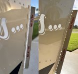
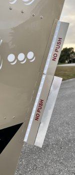
And I say significantly more P Factor because even maxing out the ground adjustable trim tab on my rudder didn't get the ball even close to being centered again while in cruise. I already had about 60% angle on my rudder trim tab with the old prop that let me fly coordinated in cruise. When I put on the E-Props, I increased the trim tab to 90% and still almost half a ball out. Not even sure how to fix that problem, other than remove the E-Props and go back to my old prop. But first, I'd like to try to get a handle on how there could have been such a change in the P Factor on the airframe.

Thanks in advance for your help.
 
Just a wild guess. It may be that your new prop is producing more of its thrust further away, toward the tip. The high speed tip then results in a stronger spiral slipstream, which is hitting the rudder and forcing it to the right. Some aircraft have a slight offset built into their vertical stabilizer, to offset this in cruise. But, obviously, that only works for the spiral slipstream produced by one particular prop.
 
I don't know if this in any way helps to solve your problem, but in a general sense it seems like in level cruise you're going to see much more impact from the prop spiral slipstream than from P factor. I can see how blade shape could effect that...
 
Increase either the width or the length (or both) of your ground adjustable rudder trim tab. A friend of mine just installed the E-Prop Constant speed prop on his Just Highlander and loves it. Works extremely well. He did not mention any slip trim need.
Ed
 
Here's a picture of my trim tab in case it helps.View attachment 55514
This is a HUGE and rather poorly functioning trim tab. If you increase its effectiveness, it will be able to be much smaller. First, NO LEAK HOLES! You can't get much of a pressure differential on a surface when it is porous. Second, this one has way too much bend. It is most likely stalled. To start with, make one the same size and shape, but with no more than 15 degrees of bend, and no holes. My guess is that will be more effective and you may be able to shorten it.
 
I don't know if this in any way helps to solve your problem, but in a general sense it seems like in level cruise you're going to see much more impact from the prop spiral slipstream than from P factor. I can see how blade shape could effect that...

Exactly right. This is a prop swirl problem, not a P-factor problem. Your new prop is apparently a lot less efficient, so it is making more swirl. It might be that your new prop is designed to be most efficient at a different operating condition than what you are cruising at, and you are just flying it way off its best design point.
 
Exactly right. This is a prop swirl problem, not a P-factor problem. Your new prop is apparently a lot less efficient, so it is making more swirl. It might be that your new prop is designed to be most efficient at a different operating condition than what you are cruising at, and you are just flying it way off its best design point.
Thanks, Steve. What do you mean by "a different operating condition?" How could I be flying it off it's best design point? The new E-Props was pitched for the proper RPM for static WOT, cruise climb, and cruise.
 
Thanks, Steve. What do you mean by "a different operating condition?" How could I be flying it off it's best design point? The new E-Props was pitched for the proper RPM for static WOT, cruise climb, and cruise.
P factor also Known as asymetrical disc loading is an angle of attack issue. Just curious, does the ball move toward The center on a descending angle of attack?
Also as mentioned earlier, the spiraling slipstream effect may have a greater effect with the newer prop.
What about preformance? Are you gaining or losing any airspeed with the new prop? Is RPM pretty much on par as with the previous prop?
Yes, on descent I believe the ball centers or even goes out a little on the other side.
Performance is strong, that is why I kept the new prop. Climb performance increased about 30% while cruise performance stayed about the same. The reason I needed a new prop is because the old Sensenich was turning too few RPMs in the climb. Normally, you'd just re-pitch it, but if we re-pitched it for higher RPM in the climb, then it would overspeed in cruise. The old Sensenich had a huge RPM spread from climb to cruise. Whereas the E-Props has a very small RPM spread and I'm turning 5,250 in the climb and 5,450 in cruise. (The old Sensenich was about 4,700 in the climb and 5,450 in cruise.)
 
Wow, this appears to be a large trim tab. I would suspect something else is going on that has not been discovered that this becomes a band-aid. I would suggest you look closely at the wings, aileron and rigging of the plane in general. JMHO.
And check wheel fairing, gear fairing alignment too. But none of that would explain a big change from one prop to another.
 
Thanks, Steve. What do you mean by "a different operating condition?" How could I be flying it off it's best design point? The new E-Props was pitched for the proper RPM for static WOT, cruise climb, and cruise.
Propellers live in what is called an "advance ratio" which is the combination of rotational speed and forward speed. A prop that takes off, climbs, and cruises great on an 80 mph biplane would not be happy at 175 mph cruise. The power absorbed (meaning the static RPM, the RPM at climb and cruise) might be the same, but the power that goes into real thrust could be very different. It is not just the basic "pitch" number but also the blade twist and blade shape that all interplay.

Full disclosure I have no direct interest in Catto Propellers, but Craig has been designing and building propellers for RVs for a long time, tweaking his designs based on lessons learned along the way. My recommendation is to see you can try a Catto. But first.....fix that horrible trim tab.
 
. But first.....fix that horrible trim tab.
Out of interest - what is the maximum deflection for a trim tab like that? Is it similar to the max deflection for the primary control surfaces, so around 30 degrees?
 
Out of interest - what is the maximum deflection for a trim tab like that? Is it similar to the max deflection for the primary control surfaces, so around 30 degrees?
30 degrees would be a maximum. More desirable to have something like 15 degrees. I'm just going on my instinct here, but I think that one with 15 degrees deflection that is twice as big as the smaller one with 30 degree deflection would have less cruise drag even if they had the same trim effect.
 
As severely displaced as the trim tab appears to be in the photos, I wonder if it could be acting more as a gurney flap than trim tab, and actually be causing the rudder to be driven in the opposite direction from what is desired?
 
Steve and company, what do we think about the new deflection angle of the trim tab and the covered holes?
 

Attachments

  • Trim.jpg
    Trim.jpg
    2.1 MB · Views: 94
  • 2.JPG
    2.JPG
    747.6 KB · Views: 94
30 degrees would be a maximum. More desirable to have something like 15 degrees. I'm just going on my instinct here, but I think that one with 15 degrees deflection that is twice as big as the smaller one with 30 degree deflection would have less cruise drag even if they had the same trim effect.
The lower trim tab is 10.5" long and the upper is 7.25" long.

Both stick out 1.5" from the rudder.

So are you suggesting get rid of the lower trim tab, add a 1.5" extension so the upper tab so it sticks out 3" from the rudder, and bend it to 15 degrees deflection? (And no holes.)
 
Also, for whatever it's worth, Tecnam still produces this plane today with the same trim tab configuration. This photo is from a 2022 and you can see it's the same dimensions with the same holes.
 

Attachments

  • Screenshot.png
    Screenshot.png
    1,014.1 KB · Views: 65
Steve and company, what do we think about the new deflection angle of the trim tab and the covered holes?
The deflection angle looks better. Hard to tell in the picture, but it looks like light still coming through all the horrible holes. Maybe they are covered with clear tape? I'm talking about the row of holes right at the bend. Tape over those if you have not already.
 
The deflection angle looks better. Hard to tell in the picture, but it looks like light still coming through all the horrible holes. I'm talking about the row of holes right at the bend. Tape over those if you have not already.
Steve, did you click to enlarge the photo above? All of the holes are covered.
 
I have solved this.

Steve, I want to thank you for the suggestions to cover the leak holes and to decrease the bend angle. I owe you a few drinks at Starbucks. Want a gift card? Doing those things, plus adding a 1.25" extension to the bottom 10-inch section has finally resulted in flying coordinated. I also reduced the bend angle in the aileron trim tab. Now it flies straight again! Interesting that I needed these modifications after installing the new prop, but it works now and that's what matters. I don't like the tape to cover the holes, so I'm going to cut and bend a new piece of sheet metal to match the final configuration I have here, get it painted, then have my A&P replace the trim tabs with the new ones that don't have the holes in them.
 

Attachments

  • Final config.JPG
    Final config.JPG
    2.6 MB · Views: 38
  • Before After.jpeg
    Before After.jpeg
    3 MB · Views: 38
For whoever is interested, I tried multiple configurations and made about half a dozen test flights before finding this final configuration that worked and got the airplane flying coordinated in cruise again, for the first time since the new prop was installed. See attached photo showing four of the different configurations tried.
 

Attachments

  • Testing.jpg
    Testing.jpg
    1.7 MB · Views: 48
For your consideration -- the trim-tab/strobe-fence in the attached image was used on an RV-7A (big rudder) to fix a 3/4 ball deflection issue in cruise. The bend is 30°.

IMG_5024.jpeg
 
SO I realize I might get the train off the track here, but why all the planes have off center balls?
Mine is slightly off because my wing incidence is off 1/16", but this shows up in trim not a ball offset.
What rigging miscue can cause a ball being off by 3/4?
 
For your consideration -- the trim-tab/strobe-fence in the attached image was used on an RV-7A (big rudder) to fix a 3/4 ball deflection issue in cruise. The bend is 30°.

View attachment 55961
I wonder if you could reduce the size & pitch of your trim tab if you located it in free flow air (about half way up the rudder), not in the turbulent flow directly aft of the fuselage.

My tabs have always been the wedge type, never larger than 1/4” thick by 3.5” high.
 
I wonder if you could reduce the size & pitch of your trim tab if you located it in free flow air (about half way up the rudder), not in the turbulent flow directly aft of the fuselage.

My tabs have always been the wedge type, never larger than 1/4” thick by 3.5” high.
Raph,

It's purpose built this way -- owner didn't like the look of the TE wedge.

Did the math on the equivalent wedge and came up with the plate size and angle. Turns out airflow really didn't matter, just the area -=> force to displace the rudder.
 
Back
Top