Fastener Analysis 101...
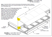
I am on step 9-6 and noticed Vans has us put the elevator skin on top of the counterbalance (CB) skin. Why would we have the elevator skin sticking up into the oncoming air stream? I called Vans tech support and they could not figure out why it is like this and confirmed their demonstrator is built this way. They could not state if there is an issue reversing this to be more aerodynamic either.
Has anyone reversed this? I don't see why it would be an issue but also am aware of not knowing if it would cause an issue down the road. I am suggesting putting the CB skin over the elevator skin to make the skins overlap in a more streamlined fashion, just like the fuselage is on 32-4 Figure 3.
Any advice on this would be appreciated.
It might be due to a strength requirement. Or it could be the designer just decided to make it that way. If it was due to a strength requirement, hopefully the discussion below will make sense on why it would be stronger.
The way the plans have the layout, the aluminum strip from the counter balance weight would be in double shear. When a joint is in double shear (i.e., a sheet on top and bottom), you essentially get double the shear strength of the rivet since both sides of the rivet (top and bottom) provide load transfer. There is a knockdown factor associated with relatively large rivet diameter to thickness ratios, such as in this case. I haven't checked the actual thicknesses of these parts but assuming they are 0.032" thick, the knockdown factor for a 3/32" rivet is 0.814 per side (see Table 8.1.2.1(b) of MIL-HDBK-5J). Since the single shear allowable for a -3 AD rivet is 217 lbf (Table 8.1.2(b)), the total shear strength of the rivet would be 353 lbf (2*0.814*217) or 62% higher than a single shear rivet (see Table 8.1.2.2(c) for the Ultimate shear strength of a -3 AD rivet = 217 lbf).
You also have to check the bearing strength of the sheet. Alclad 2024-T3 sheet has an A-Basis allowable of Fbru = 121 ksi (e/D = 2, Table 3.2.3.0(e1)). A-Basis is a statistical knockdown that is normally used for primary structure (this would be considered primary structure since it's flight critical. See Appendix A, section A.3 for more info). Since the hole size is 0.098", and the sheet is 0.032" thick, the bearing strength of the sheet is 379 lbf (0.098*.032*121,000). That means that the rivet will shear (353 lbf) before the sheet will "bear out" (379 lbf). You normally prefer to have a "fastener joint" fail via bearing vs. failing by shear. If a rivet let's go in shear, all of the load that the rivet was carrying now has to be "picked up" by the adjoining rivets. If a rivet "bears out" (i.e., it "yields"), it will continue to transfer the load it was seeing when it yields. However, any additional load in the joint will be transferred to the adjoining rivets. This results in a joint that has some "give" to it. It shouldn't completely fail until all of the fasteners in the joint reach their ultimate strength. With a "shear first" type joint typically the joint fails when the first fastener fails. However, I would expect that the overall strength of the joint is much higher than what it actually sees. Even though the failure mode is not ideal, the joint is probably much stronger than what it needs to be so it really doesn't matter what the failure mode is.
If you place the sheet "on top", then the fastener is in "single shear" (i.e., a sheet on only one side). That would make the rivet shear at 217 lbf. So by placing the sheet in double shear (like the plans suggest), the strength of a particular rivet is 62% higher.
I hope all of this makes sense. I know it's a lot to swallow so to speak. There's more to this to figure out the actual load on a specific fastener, but this is what a structural engineer looks at to find the strength of a single fastener in a "mechanically fastened joint".
Oh, and BTW, it doesn't matter if the joint has primer in it or not...
")
Jeff