What's new
Van's Air Force

Don't miss anything! Register now for full access to the definitive RV support community.

EFI Fuel Pump Failure Risk

How do you use your fuel pumps?

  • SDS System: 1 Pump on for TO

    Votes: 6 14.3%
  • SDS System: 2 pumps on for TO

    Votes: 18 42.9%
  • EFII System & Bus Manager: 1 pump on for TO

    Votes: 11 26.2%
  • EFII System & Bus Manager: 2 pumps on for TO

    Votes: 1 2.4%
  • EFII System NO bus manager: 1 pump on for TO

    Votes: 3 7.1%
  • EFII System NO bus manager: 2 pumps on for TO

    Votes: 3 7.1%

  • Total voters
    42

TASEsq

Well Known Member
Patron
I’m in the very early learning stages of an electrical design to support an EFII system - at this stage unsure on SDS or EFII.

It may not be popular opinion (and not trying to open a debate on this) but feel a single box power system such as the vertical power PPS or EFII bus manager are single points of failure and I don’t think I want to be IFR with a family member relying on a magic box to ensure electrons to the injectors. However, the bus manager comes with functionality to ensure a backup if the primary fuel pump should fail - without this there is no auto-switching to the backup fuel pump if the primary pump fails.

No problem I figured, I would just run 2 pumps at takeoff eliminating the consequences of a pump failing at 300ft - and I was surprised to learn from Robert at EFII that this was not a good idea. I don’t know what Ross thinks for SDS. Apparently, the extra suction can cause a drop in pressure on the suction side, reducing your margins toward vaporisation and cavitation of the pump.

I hope Robert doesn’t mind me quoting him here but he can explain it better than me:
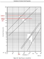
The lower the pressure in the suction end of the system, the closer you are to cavitating the fuel (forcing the fuel to vaporize).
When the pressure of a liquid gets down to the vapor pressure of the liquid, the liquid will start to change to its vapor state.
Auto gas will start to change to vapor at a pressure equivalent to about 10,000ft altitude, avgas does this at 18,000ft.
If you pull hard on the suction side of a fuel system, vaporization will occur at a lower altitude - you lose "margin" on how far you are away from cavitation in any given flight condition when the pressure of the fuel is lowered.

This also got me thinking whether these systems are worth the effort - my main reason for thinking about it was the support for auto gas in a io390 engine in the future (when avgas doesn’t exist anymore). But if autogas vaporises at 10,000 ft anyway maybe there is no point going ahead with this?

Obviously I wouldn’t be taking off at 10,000 ft etc running the 2 pumps but I take Robert’s point about reducing the margin.

So for SDS/EFII users (I am assuming an essentially identical system design with regard to fuel delivery to the engine):
1. How many people run 2 pumps at once on takeoff? Have you seen any issues?
2. Is there another simple solution to activate a second pump if fuel pressure drops in the first?
3. Am I overthinking this - the walbro pumps are apparently very reliable. Perhaps just running one pump is acceptable?
4. Does anyone run SDS / EFII using auto gas in a io390? (I am building a -14 so don’t have a lot of engine choice).


Thanks in advance - apologies if the questions are basic or ignorant! Just trying to learn about the systems at this stage and work out whether there is value in it for my build.
 
Last edited:
Hi Trent
As you know the engine has its own mechanical pump. The only reason you have an electric fuel pump is to backup the mechanical fuel pump in case it should fail. That’s why you turn the pump ON during takeoff and landing. To have both pumps fail at the same time is like hitting the lottery without wanting to be the winner. Obviously before you start your engine you turn ON the pump to prime the engine so you know before every flight it’s working. For the paranoid I guess you can put a second pump in line with the first one. I don’t see why it would cause enough of a pressure drop where the fuel vaporization is going to significantly change in altitude (is it going to vaporize at 8K? I doubt it). Also how often are you going to even fly above 12,500?
 
Last edited:
Daren---the SDS/EFii systems delete the engine mechanical pump, and use the electric pumps only. Wouldnt it be nice if there was a gear dive mechanical pump, like a Romec, adjusted to the 40-45Lbs? While that would provide the fuel pressure and delivery to the injectors, well the injectors are still electronic, and need the computers to provide the opening/closing timing. So----still electrically dependent.

Probably and non issue--
Tom
 
We run an SDS system and use both pumps at T/O and landing. Haven't had an issue yet. I believe the highest takeoff was out of Reno in the summer with a DA close to 9k feet. Per the SDS installation instructions, fuel pumps, injectors and ecu should have dedicated physical circuit breakers and not be run through the bus manager. This removes the single point of failure you mentioned. However, if you don't run them direct to the battery (I don't), you'll still have the main contactor as your single point of failure.

There was a thread on here a few months ago about turning on the 2nd pump automatically but I can't find it right now. My initial thought would be to tie the 2nd pump into the master warning output pin on the gea 24 or dynon equivalent and set a red alert for fuel pressure below ~20psi. You would need an external relay but what you're aiming for is if fuel pump 1 is turned on and the master caution is on, then energize fuel pump 2. It's a very solvable problem with a bit of wiring.

I would also like to understand EFII claims on his vapor pressure margin. There are AVGAS airplanes that fly well into the mid 20 flight levels, so if 18k ft is the transition altitude for AVGAS, how do they possible climb that high without vaporizing all their fuel? There have been a few people on here that have had vapor issues with the fuel system, and almost every one was solved by removing hard 90s on the feed side of the pump. I don't think I've ever seen a post that claimed the 2nd pump was causing the issues.
 
Last edited:
fuel pumps

Running EFII on my -10.

Single pump operation with the bus manager auto switch, which is tested at every start up. I have tested the auto switch during phase 1 by pulling the #1 pump c/b...the pump switched and the engine didn't miss a beat.

It would be simple enough to fabricate an auto switching circuit using a relay and pressure sensor much like the bus manager.

If you drill down far enough, you will always find a single point failure; how many injectors do you have per cylinder? You could have a half dozen fuel pumps and an injector failure would negate all of your perceived backups.

Point is, it is all about risk mitigation in relation to your personal risk aversion.
 
I have an SDS system on my Subaru H6 (RV-7A). Both pumps and the dual feeds to the ECU/EFI come from always hot battery busses - dual batteries of course :cool:
I have taken off with both pumps running with no issue, but my normal operation is one pump, and I’m ‘spring loaded’ mentally to turn on the other pump at the first sign of any hiccup from the engine.
This has worked well since 2008.

Early on, an automatic failover (pressure switch/relay) was recommended, but many folks had problems with the pressure switch, so most of us just do it manually.
 
Last edited:
I run the EFII System 32 with its Bus Manager.
I have two batteries, both are hot wired to the Bus Manager as per the installation instructions.
If the internal EC board malfunctions, a switch bypass will feed the electrons directly to the ECUs and pumps.

Only one pump is on at the same time.

The Bus Manager is adjusted to a set fuel pressure that automatically and instantly switches to the #2 pump if the pressure falls below that set number when the fuel pump switch is on #1/AUTO.
My switching pressure was a bit high at first and when flaring to land and retarding to idle, sometimes the #2 pump would kick in.
If it weren't for the annunciator light on my panel, I would not notice.
 
I'm running the SDS system on my IO360, and routinely operate with both pumps running, for takeoff/landing and for switching between pumps. I also fly with 93 octane autofuel, with ethanol, and routinely fly in the mid-upper teens without issues.

You will need to make sure you have as low a pressure drop as possible between the tank pickup and the pump suction - that's true - but for the rest of Roberts statement, I think I'll have to just raise an eyebrow and say no more.
 
Hundreds of our customers run both pumps for TO and landing and below 1000 AGL, switch off one pump in cruise. Haven't heard of any issues like surmised here.

I'd always run 2 pumps down low, one up high. We've seen 6 failures in a bit over 900,000 flight hours. It'd be a shame to lose an airplane because you didn't have a backup pump installed.

Run separate switches and breakers for each pump. Don't run any EFI stuff through the VPX.

Not sure where the erroneous info on fuel vapor comes from but I'll inject some actual factual real world data here.

I've flown a PA31P at 22,000-24,000 feet a bunch of times years ago. Still here to tell you the story. A bunch of avgas burning GA aircraft are certified to 25,000 feet...

The altitude record on avgas with non-pressurized tanks is 47,000 feet- A highly modified RV in fact.

Here is a screenshot from a customer RV-9A running SDS and mogas 21,000 feet DA (thanks Greg):
 

Attachments

  • greg2.png
    greg2.png
    470.1 KB · Views: 157
Last edited:
I’m in the very early learning stages of an electrical design to support an EFII system - at this stage unsure on SDS or EFII.


Obviously I wouldn’t be taking off at 10,000 ft etc running the 2 pumps but I take Robert’s point about reducing the margin.
.

You might.. if you ever visit Leadvillle!!
 
There are AVGAS airplanes that fly well into the mid 20 flight levels, so if 18k ft is the transition altitude for AVGAS, how do they possible climb that high without vaporizing all their fuel?

Fuel is a mixture of volatile compounds, each with its own vapor pressure, so it is difficult to assign a single pressure (i.e. altitude) to bubble formation. It's also highly dependent on temperature, not just pressure.

However, there are standards allowing some quantification. I've attached a chart below, from the CRC's Handbook of Aviation Fuel Properties.

18000 ft would be 50 kPa local pressure, so it would take 104F to boil fuel in the tanks. Eventually our aluminum tank contents would assume the standard day ambient temperature of -5F.

Fuel cooling would lag ambient in a climb. Lets assume 20F fuel temperature. The chart says the pump would need to pull inlet pressure down to about 24 kPa (3.5 psi), or about half of ambient.

Lesson is simple. Keep the inlet flow unrestricted and cool. I'm not saying it's easy, but it's the design goal.
.
 

Attachments

  • Fuel Vapor Pressure.jpg
    Fuel Vapor Pressure.jpg
    148 KB · Views: 47
Other than the VPX being a potential single point failure, what’s the rationale?

VPX electronic breakers trip on peak current rather than average current as a traditional thermo breaker does. The injectors and coil pack in particular have high peak current but low average current. You have to set trip points very high as a result. We put out a caution SB on this aspect in 2015 after an incident occurred.
 
VPX electronic breakers trip on peak current rather than average current as a traditional thermo breaker does. The injectors and coil pack in particular have high peak current but low average current. You have to set trip points very high as a result. We put out a caution SB on this aspect in 2015 after an incident occurred.

So this is more of a potential concern for the injectors and coil packs rather than the ECU’s and fuel pumps?
 
So this is more of a potential concern for the injectors and coil packs rather than the ECU’s and fuel pumps?

Right, ECU current is quite constant.

Fuel pumps have a lot of inductance so initial current is quite high on startup for 1/2 second, after that, quite constant around 4.5 to 6 amps depending on which Walbro pump you have.

If the pump doesn't pop the breaker when you turn it on, it should be fine after that.

Roger that. It’d be nice to have as much of the EFI’s system current draw being measured by the VPX and include in the total ships power draw.
Thanks Ross!
 
Roger that. It’d be nice to have as much of the EFI’s system current draw being measured by the VPX and include in the total ships power draw.
Thanks Ross!

I've gotten around that by having a current shunt on the alternator. Once the battery finishes charging, the alternator output is the total system current draw. On my system the difference between VPX loads and alternator output is about 7 amps with one pump on, about 11 with both.
 
I've gotten around that by having a current shunt on the alternator. Once the battery finishes charging, the alternator output is the total system current draw. On my system the difference between VPX loads and alternator output is about 7 amps with one pump on, about 11 with both.

Good information Paul….thanks!
 
EFII load

I've gotten around that by having a current shunt on the alternator. Once the battery finishes charging, the alternator output is the total system current draw. On my system the difference between VPX loads and alternator output is about 7 amps with one pump on, about 11 with both.

Since I run 2 independent busses with 2 batteries 2 alternators with a shunt on each alternator I can also see the load each bus is pulling after the batteries are topped off. Each bus runs at 14.2 volts. The engine bus pulls 12 amps and as EFII and SDS recommend not on my VP system. This is for a 390. I’m assuming same system on a 540 will pull slightly higher amps. I’m only running one pump at a time with automatic switchover using the EFII Bus Manager. I pulled the pump breaker several times at first on the ground and the EFIS historical data recorded every second was not fast enough to capture the event. (Fuel pressure) and once in the air at altitude over my airport at 24 squared and again the EFIS did not capture the event. (There was no stubble or hesitation of the engine).

I think Roberts is saying by running 2 pumps the margin of vapor pressure delta decreases with twice the flow or at least higher flow rates. The fuel selector valve most of us use was designed for 200 hp or less, Andair FS2020):

"The FS2020 is a 3-way 3/8” Duplex Fuel Selector designed for fuel-injected engines up to 200HP." From the Andair web site.

Obviously the fuel pump can output enough for higher HP (Around 35 gpm at 35 psi) but the issue is getting this much flow to the suction side of the pump. This is why Andair designed the FS2520 with the same size discharge but AN8 fittings on the suction side. It’s the same reason hard 90’s are frowned upon in the suction. The higher flow rates created by running 2 pumps creates higher pressure drops on the suction side of the pump and reduces the margin bubbles will form and or cavitation.

Both systems (SDS and EFII) are very good and robust in my humble opinion. The fuel burns I have seen with these systems is exceptional. Personally I can run at 7.5 gpm LOP at 163 knots and 10,000 ft. After almost 400 hrs my plugs still look brand new. I also completely understand why a lot of builders shy away from electron dependent engines. It’s about personal risk management. (I don’t fly at night anymore regardless if the engine is electron dependent or not) I do worry about buyers obtaining one of these systems and not thoroughly understanding the design. Add to this lithium batteries that might not also be well understood and you potentially could have a perfect storm.

Good discussion and thanks for the inputs.
 
Last edited:
Most RV-10s are using the same FS20 fuel selector and up to 300hp.

The engine is easily fed by -6. Haven't seen any issues with both pumps on. We used to be cautious about this years back as well but practice showed this not to be a concern.

Look at the ID of the fittings on the TI (Walbro) pumps- combined area of both is less than the area of -6 line.
 
Last edited:
ΔP = 0.0668 μv ÷ D²

Most RV-10s are using the same FS20 fuel selector and up 300hp.

The engine is easily fed by -6. Haven't seen any issues with both pumps on. We used to be cautious about this years back as well but practice showed this not to be a concern.

Look at the ID of the fittings on the TI (Walbro) pumps- combined area of both is less than the area of -6 line.

True but Delta P is = pressure drop per 100 ft of pipe. Given the length of the inlet fittings (very short) this small cross section does not induce that large of pressure drop and so we get away with it, in most applications. Hard 90's probably also have larger cross sections than the ID fittings of the pumps (I don't use or have one so not sure) but we try not to use them. It's all about buffer of potential error. The larger the gap the better. Most of the time it works until a set of conditions arise (warmer fuel temps on a hot summer day in New Mexico (above ground tanks that we needed a large % of our tanks filled), combined with slightly higher altitude that we did not expect along with a petrochemical facility getting rid of their winter blend fuel mixture (or mogas with a richer ethanol blend) later in the season than typical that MIGHT get us in trouble). It's all about probability and do I feel lucky or is the risk factor acceptable? Potentially doubling suction pressure (negative) is bound to create more flow and increase pressure drop reducing vapor pressure and margin of buffer.
 
Last edited:
True but Delta P is = pressure drop per 100 ft of pipe. Given the length of the inlet fittings (very short) this small cross section does not induce that large of pressure drop and so we get away with it, in most applications. Hard 90's probably also have larger cross sections than the ID fittings of the pumps (I don't use or have one so not sure) but we try not to use them. It's all about buffer of potential error. The larger the gap the better. Most of the time it works until a set of conditions arise (warmer fuel temps on a hot summer day in New Mexico, combined with slightly higher altitude that we did not expect along with a petrochemical facility getting rid of their winter blend fuel mixture (or mogas with a richer ethanol blend) later in the season than typical that MIGHT get us in trouble). It's all about probability and do I feel lucky or is the risk factor acceptable? Potentially doubling suction pressure (negative) is bound to create more flow and increase pressure drop reducing vapor pressure and margin of buffer.

All true, however practice (many hundreds of thousands of flight hours in hot climates) shows that there is no problem with the recommended SDS layout at least. We use straight fittings in our pump modules while others use banjo fittings. No idea if these have more or less flow restriction.

Lots of things in our single engined aircraft MIGHT get us in trouble. If we considered all of them, maybe none of us would go flying.

Pretty sure Andy is using a std FS20 valve on his racer at 90 gph. Shows how much margin there is.
 

Attachments

  • andy5.jpg
    andy5.jpg
    182.6 KB · Views: 75
It's not too significant, but if you're using an FS2020 or similar duplex valve, especially with right angle fittings, there may be a very small total head benefit by running the feed lines through the lower valve and the return lines through the upper valve. About 100ft extra altitude before you hit your cavitation pressure :)
 
Last edited:
It's all about probability and do I feel lucky or is the risk factor acceptable? Potentially doubling suction pressure (negative) is bound to create more flow and increase pressure drop reducing vapor pressure and margin of buffer.

Would it create more flow? There is a pressure regulator in the system which is likely a restrictor. Would this not restrict any extra flow?

I've experienced this in a smoke system - the pump we chose had too high an output. When we restricted the flow to the engine, there was back pressure on the pump which increased the duty of the pump and increased the amps load. To the point it blew the breaker. To fix it, we created a loop to allow the output of the pump to return to the input side, prior to the restriction. This way the system builds pressure without loading up the pump. I am not sure the fuel regulator in the SDS or EFII is analogous to this however.

What is the result if vaporisation occurred? Say the fuel vaporises at the suction side, would one or both pumps cavitate and destroy the pumps? Would the engine stop? Just trying to work out if this did happen (as you say with unforeseen rare alignment of the fuel gods etc) what the outcome would be? I don't know how to do the math, but i wonder if pressure drop can be calculated for a -6 line? (is it even possible to get to the 3.5 psi as Dan H mentioned).

I would imagine if one pump was to be turned off the issue would resolve immediately?

I suppose balancing the risk of pump failure versus pump cavitation is the question. In a certified world there would just be an AFM limitation (do not operate second pump for take-offs and landings above 8000ft or 40c - or something). I would be happy to do something like that - establish a safe limit during flight testing.


If you drill down far enough, you will always find a single point failure; how many injectors do you have per cylinder? You could have a half dozen fuel pumps and an injector failure would negate all of your perceived backups.

Point is, it is all about risk mitigation in relation to your personal risk aversion.

True - but all the injectors won't fail at once. If the single running fuel pump fails the engine stops until you get the other pump turned on. If one injector fails at 300ft, the engine is going to run horribly but surely 50% power at least?

Early on, an automatic failover (pressure switch/relay) was recommended, but many folks had problems with the pressure switch, so most of us just do it manually.

I wonder what the issues were? Does anyone know of a fuel pressure 'switch'? aka, something which could be installed in the outlet side of the pump module, calibrated to 30psi or something, and which could be used to drive a 'low fuel pressure' red light etc? (or indeed, ground a relay to turn on the second pump?)

I like the idea of using the GEA24 generated master warning discrete to ground a relay and turn on the pump, but i don't believe you can isolate it to just fuel pressure. It would activate the pump for the canopy being open etc?

I've flown a PA31P at 22,000-24,000 feet a bunch of times years ago. Still here to tell you the story. A bunch of avgas burning GA aircraft are certified to 25,000 feet...

Come to think of it, i took a C402 up to the mid twenties on a photo sortie one day. Didn't miss a beat. The only issue i remember was keeping the cylinders cool. Needed to be full rich to cool the engines down.

Thank you all for your input. It's fuelling my thinking cells and i am learning a lot.

At this stage, based on this feedback, i think the simplest system is just 2 switches driving 2 relays to control the pumps. I would wire the primary relay such that the pump runs on the normally closed contacts (aka it needs to be grounded to turn OFF the pump). For the second pump, i was wondering whether it could be run the same way? Is there any issue with flying all day long with a relay coil powered on, keeping the pump turned off?

Otherwise, i could wire it the opposite way - such that the second pump is wired onto the normally open contacts (aka the relay coil needs to be grounded to turn on the pump).

I think the idea of relays is a good one in this case - means i don't have to have 15a switches, and also don't need largish wires to the left side of the panel; the way i would wire it would eliminate any issue with the relay failing - the primary pump would just stay on.

One further question for the SDS users - does anyone have any concerns around the DUAL ECU's being in the same physical case? Could the failure in one board affect the other board? Is it possible to run 2 ECU's, but use 2 separate ECU boxes?
 
I run the dual pump SDS module and manually switch the second pump on for TO and landing. I also routinely fly from high altitude airports, in extremely hot air temps (120+), and I also run "california blend" corner gas station regular unleaded. I routinely see 28+ GPH on initial climb. One would be hard pressed to find a more challenging fuel delivery example than I have.

No issues whatsoever.
 
Last edited:
Les Kearney does annunciator warnings through the G3X for fuel pump warnings. Pretty slick.

Most folks are just using heavy duty switches directly for the pumps. I'd expect relays would be fine too but more parts to fail.

As for both boards in one box, on the EM-6, we have serial comm between the boards now for various monitoring and data transfer purposes so you can't have separate boxes any more. Haven't seen a problem with one board frying the other yet. Folks have always been able to get back on one or the other if there was an issue.
 
...No problem I figured, I would just run 2 pumps at takeoff eliminating the consequences of a pump failing at 300ft - and I was surprised to learn from Robert at EFII that this was not a good idea.

So for SDS/EFII users (I am assuming an essentially identical system design with regard to fuel delivery to the engine):
1. How many people run 2 pumps at once on takeoff? Have you seen any issues?
2. Is there another simple solution to activate a second pump if fuel pressure drops in the first?
3. Am I overthinking this - the walbro pumps are apparently very reliable. Perhaps just running one pump is acceptable?
4. Does anyone run SDS / EFII using auto gas in a io390? (I am building a -14 so don’t have a lot of engine choice).


Thanks in advance - apologies if the questions are basic or ignorant! Just trying to learn about the systems at this stage and work out whether there is value in it for my build.

In the event my earlier post was too cryptic, let me address your concerns directly:

1. I run 2 pumps at once every flight (TO/LDG). No issue
2. A button/switch. Just like you were likely taught from day one in flight training (GUMP)
3. I have thousands of hours in automobiles with the same pumps with no failure, but if I have 2 available, I'll use both in a critical phase of flight.
4. Yes, auto gas. No, not a 390, but a 540.

If a Mfg of a system tells you his system is unreliable in a dual pump configuration and another can show his is reliable in that same configuration, kind of narrows down the choices, doesn't it?

Just had to get that dig in, didn’t you?
 
Stated much earlier was something like 'brand x fuel pumps are very reliable'.

Many years ago I read an accident report on a V6 powered experimental airplane. No dual ignition. The primary wire to the coil broke off in flight causing a bad off field landing. I think we'd all agree that automotive coils are very reliable. But if the wire falls off (fatigue, bad crimp, whatever) then it doesn't matter how reliable the coil (or fuel pump) is.

I caught a similar problem looking at a local plane... dual ignition, dual coils. All good? Single power wire feeding both coil switches.

In a 100% electrically dependent airplane every effort needs to be made to eliminate EVERY single point failure. That's not easy. But we need to try.
 
Would it create more flow? There is a pressure regulator in the system which is likely a restrictor. Would this not restrict any extra flow?

In general, the 2nd pump will add a few psi to the system, and until you get to critical flow velocity, more pressure will be more flow. The pressure regulator isn't a fixed orifice and is more akin to a diaphragm/spring design. Since the 2nd pump only increases the pressure a few psi, the flow increase will be a very small percentage.

What is the result if vaporisation occurred? Say the fuel vaporises at the suction side, would one or both pumps cavitate and destroy the pumps? Would the engine stop? Just trying to work out if this did happen (as you say with unforeseen rare alignment of the fuel gods etc) what the outcome would be? I don't know how to do the math, but i wonder if pressure drop can be calculated for a -6 line? (is it even possible to get to the 3.5 psi as Dan H mentioned).

I would imagine if one pump was to be turned off the issue would resolve immediately?

You'll likely get small pockets of cavitation in critical areas. Hopefully you'll just circulate the bubbles back to the tank without noticing. If it progresses, you'll get engine stumbling. If it gets critical, you'll lose prime on the pump and the engine will die. These pumps are self-priming though, so when the altitude gets lower the pumps will likely re-prime, pump the bubbles out of the system back into the tank, and the engine will restart. The major risk is if you don't have the room to descend.

I wonder what the issues were? Does anyone know of a fuel pressure 'switch'? aka, something which could be installed in the outlet side of the pump module, calibrated to 30psi or something, and which could be used to drive a 'low fuel pressure' red light etc? (or indeed, ground a relay to turn on the second pump?)

https://www.summitracing.com/search/part-type/pressure-safety-switches/thread-size/1-8-in-npt

I like the idea of using the GEA24 generated master warning discrete to ground a relay and turn on the pump, but i don't believe you can isolate it to just fuel pressure. It would activate the pump for the canopy being open etc?

This is true, but there are only a very small handful of situations where turning on pump 2 will cause the situation to get worse. The 2 main ones that I can think of are engine fire and total loss of battery/alternator. In either case, take 10 seconds to assess the situation, and then pull the breaker for the 2nd pump. So while pump 2 isn't required for all master warnings, it likely won't make the situation worse either.

I think the idea of relays is a good one in this case - means i don't have to have 15a switches, and also don't need largish wires to the left side of the panel; the way i would wire it would eliminate any issue with the relay failing - the primary pump would just stay on.

Most aircraft grade toggle switches sold on spruce or wicks are rated for 20 amps. Personally I would just wire the power through the switch and remove the relays. Just one more part to fail. If you go with a switch that can't handle the current, then relays are fine. You can keep the coil energized all day as long as the relay is rated for continuous use.

One further question for the SDS users - does anyone have any concerns around the DUAL ECU's being in the same physical case? Could the failure in one board affect the other board? Is it possible to run 2 ECU's, but use 2 separate ECU boxes?

As Ross said, the boards are isolated so there isn't much chance of them taking each other out. Physical separation is taken into account during risk assessment of systems, but normally being in close proximity is associated with physical damage from an external source. Don't put all your hydraulic lines right next to each other in the same wheel well type situations. I think to get to both boards on an SDS you would need a fire or major water leak. Even then, I believe the SDS is mostly sealed so water ingress isn't a huge concern. Or maybe if you just started pulling random cables out from behind the panel in flight you might get both SDS harnesses in a single grab since they're close to each other. But overall, I don't think the fact that the boards are in a single box is a huge drawback.
 
Last edited:
I think the idea of relays is a good one in this case - means i don't have to have 15a switches, and also don't need largish wires to the left side of the panel; the way i would wire it would eliminate any issue with the relay failing - the primary pump would just stay on.

I don't think you really need relays. The fuel pumps in the SDs installation are Walbro GSL393, with characteristics as shown. In this application it will draw about 13.5V/6A.

A SPST switch which meets MS24523-22 or MS24658-22, such as the Honeywell 1TL1-2, is rated at 28V/15A for inductive loads, so it will handle the pump loads several times over, even allowing for high starting currents.

As for wire size, 18AWG will handle these loads, and is only 0.82mm^2 cross-section area, so it isn't a largish wire.

Of course, none of this means you can't use relays if you want to, but there's no compelling electrical reason to do so.
 

Attachments

  • GSL393-Flow-Chart.jpg
    GSL393-Flow-Chart.jpg
    112.4 KB · Views: 63
Of course, none of this means you can't use relays if you want to, but there's no compelling electrical reason to do so.

Those were the switch type I was considering anyway I think - thanks for the input. I guess it depends on whether I end up with fuse panels (busman etc) for each engine bus somewhere on the sub panel, or whether I end up with the fuel pump breakers on the -14’s angled CB panel (which is right near the fuel pumps and would mean a run up to the switches and back again).
 
I know there are strong opinions about this, but if you use Tyco W31 series switchable circuit breakers, you get something that functions similarly to the Honeywell switches you're looking at while also providing circuit protection without needing a separate fuse panel, which is handy if space is an issue.

- mark
 

Interesting idea - thanks!

Looks like these are designed to turn off the Nos in a car when the fuel pressure drops too low. Perfect for the purpose of running a warning light or grounding a relay coil to turn on a pump.

What psi would everyone say is a good value to prevent nuisance tripping but have the pump come on asap if the primary pump fails?

They look like they come in a huge range of pressure ranges.
 
Les Kearney does annunciator warnings through the G3X for fuel pump warnings. Pretty slick.

Most folks are just using heavy duty switches directly for the pumps. I'd expect relays would be fine too but more parts to fail.

As for both boards in one box, on the EM-6, we have serial comm between the boards now for various monitoring and data transfer purposes so you can't have separate boxes any more. Haven't seen a problem with one board frying the other yet. Folks have always been able to get back on one or the other if there was an issue.

Thanks for your feedback Ross. Great to hear from vendors directly. I appreciate your time.
 
I know there are strong opinions about this, but if you use Tyco W31 series switchable circuit breakers, you get something that functions similarly to the Honeywell switches you're looking at while also providing circuit protection without needing a separate fuse panel, which is handy if space is an issue.

- mark

I’d guess most of those strong opinions are like mine, based on a first hand experience of a failure of an important device combined with a very disconcerting smoky experience. I’ll look for the photo.
Not an if, it’s a when. They junk I reckon. Make more space I say!
 
So the OP asked about the postulated concern with running both pumps and the low altitudes stated where vapor formation would be problematical.

I offered that many certified aircraft fly at 25,000 feet without issues and that the altitude record set by Bruce Bohannon in Flyin' Tiger is 47,000 feet with avgas (non-pressurized tanks). This is more than double the stated altitude in the post.

We've had 2 SDS users post that they routinely fly into the high teens and up to 20,000 feet with mogas on hot days and use both pumps near the ground without issue. The stated concern was at only 10,000 feet in the OP.

Dave Anders routinely flies at 17.5, operates from Leadville frequently and has flown in OATs as high as 118F- no issues.

I've been flying with mogas since 2009, up to 15.5- no issues.

You don't need 2 pumps on in cruise. You're just wasting power and pump life circulating excess fuel for no gain. I alternate pumps used in cruise- pump 1 on odd days, pump 2 on even days to split pump wear.

In my world, real world experience trumps unsubstantiated theory. To quote Richard P. Feynman “It doesn’t matter how beautiful your theory is, it doesn’t matter how smart you are, if it doesn’t agree with experiment, it’s wrong”

You folks can go on postulating what you think might happen while the rest of us flying this stuff go about our daily lives. I know what works with SDS. I don't know about other brands. I suggest you do a simple experiment on the next flight- at high altitude, turn on both pumps and see what happens...

Report back here.
 
True but Delta P is = pressure drop per 100 ft of pipe. Given the length of the inlet fittings (very short) this small cross section does not induce that large of pressure drop and so we get away with it, in most applications. Hard 90's probably also have larger cross sections than the ID fittings of the pumps (I don't use or have one so not sure) but we try not to use them.......

Your equation and approach here isn't really applicable here. Losses occur in anything that has friction from a orifice plate to X100s of feet of pipe. The loss/per is mainly used for comparative purposes; trying to determine where the capitol investment costs and operating cost lines intersect -> $/pipe diameter over the life of the investment.

Losses are a function of the fifth power of the tube/pipe Di if turbulent flow where friction factor becomes a bigger deal. Closer to fourth power if things stay slow and laminar. Either way, the losses add up quickly. Ex = halving the tube size increases the loss 32X, conservative case. Likewise going from a -6 to -8 tube cuts the losses by ~75%.

Would it create more flow? There is a pressure regulator in the system which is likely a restrictor. Would this not restrict any extra flow?

These are positive displacement pumps which theoretically have the same flow (at a given RPM) regardless of pressure, Pump seals aren't perfect so some "slip" occurs especially for low viscosity things like fuel. The motor powering it will also bog down a little, Either way, the design point would be 70 gph up to the back pressure reg.

That's all I've got from the way back machine.

Edit = some images from Crane Technical Paper 410. These include a table of validated numbers to back the calcs. Mr. Farnham tends to get pissed at me as I believe he assumes we always operate at different ends of the spectrum. I'm an anal b@#$d. I have to prove it to myself before I consider it but I firmly believe that in the cycle of:

design->development->testing->validation-> field follow

not giving all of these phases the proper respect will: at best cost you time, certainly will cost you more money, ultimately could cause someone to get hurt or worse. The butterfly effect is waiting to rear its unpredictable head. Someone copies a long verified fuel system design but their exhaust flow profile is different and causes the suction portion of their fuel system to experience more heat. I've experienced a ton of unintended consequences in my lifetime. I like to know what margins are available whenever I can. Stay safe.

Cheers boys.
 

Attachments

  • IMG_8471.jpg
    IMG_8471.jpg
    230.9 KB · Views: 33
  • IMG_8472.jpg
    IMG_8472.jpg
    276.5 KB · Views: 35
  • IMG_8473.jpg
    IMG_8473.jpg
    504.1 KB · Views: 34
Last edited:
While we are on the fuel system topic, I'd like to relate something we've now seen 4 times which is much more of a concern: debris in the fuel filters and/or tank vents.

These 4 incidents all played out about the same way- engine started leaning out either mildly or seriously. A reduction in throttle in all cases reduced the lean condition and all managed to limp or cruise back to the airport.

Debris/ goop was found to be plugging the filter elements on 3 of these and one had Mud Dauber debris plugging the vent fittings.

Source of the filter debris was undetermined- usually brown or black. All of these planes had be flown for over 100 hours, 2 had already had the filters inspected, cleaned or changed so it wasn't construction debris. Be sure if you use rubber lined hoses that the lining isn't disintegrating. I prefer Teflon or aluminum.

On installations with a pre-filter in each wing root, you can switch to the other tank if there is fuel there.

Lesson here is don't skimp on filter maintenance and check those fuel vents during pre-flight. This stuff can hurt you.
 
Last edited:
These are positive displacement pumps which theoretically have the same flow (at a given RPM) regardless of pressure, Pump seals aren't perfect so some "slip" occurs especially for low viscosity things like fuel. The motor powering it will also bog down a little, Either way, the design point would be 70 gph up to the back pressure reg.

This is incorrect in this case. Please reference the flow/ pressure chart a few posts above. Flow certainly drops substantially with increasing pressure and motor current goes way up.
 
Interesting idea - thanks!

What psi would everyone say is a good value to prevent nuisance tripping but have the pump come on asap if the primary pump fails? .

Its a 40psi pressure regulator and tied to vacuum on a 1:1 ratio. If you pull full vacuum on the intake, it should regulate down 14psi and hold steady around 26psi. I normally see 22-25psi on the ground at idle, so there's some wiggle room for real world adjustments. If you get under 20psi, something is probably wrong.

If you tie the 2nd pump to the warning light and want it to come on automatically, you'll need to have a latching relay, otherwise when the pump kicks on the pressure will rise, the light will go out, and the pump will turn off. Rinse and repeat.
 
Last edited:
This is incorrect in this case. Please reference the flow/ pressure chart a few posts above. Flow certainly drops substantially with increasing pressure and motor current goes way up.

Went to the end of the thread, My bad.

That's a fairly sizable amount of pump slip. Some is expected no matter what and the lower the viscosity, the more you expect. That said, this appears to be excessive. Maybe they chose to forgo some seals or needed to because MoGas lubricity is so low. Avgas is worse.

Something else that looks off. For this type of pump, power is linear with pressure and flow ->HP = GPM*PSIG/1714. If one is decreasing linearly and the other increasing linearly, the current (also linear with theoretic HP) line is surprisingly straight. Cool.

Do the pumps have an internal relief or bleed to ensure prevent deadheading?
 
Do the pumps have an internal relief or bleed to ensure prevent deadheading?

Yes, internal relief starts around 100 psi and fully on around 110. You can see the big dip in the curve here.

Also have internal check valves so in a dual pump module, no backfeed with only one pump on.

Note the Walbro charts were developed with Stoddard Solvent, gasoline is a bit different viscosity wise and would change all the curves a bit.

They probably (purposely) build a "loose" pump to prevent wear/maintain performance life while sacrificing some pressure/flow performance; or, as mentioned have a small internal bleed for cooling purposes. You said they utilize a relief for dead-head protection. I should have seen that and known it wasn’t pressure collapse from cavitation. The current draw would have come down. The flow-pressure line on gasoline will be steeper because of the relative viscosities. Some non quantified examples from a well respected pump manufacturer that show viscosity effects versus other characteristics.

Edit = diagrams added, if anyone cares.
 

Attachments

  • IMG_8474.jpg
    IMG_8474.jpg
    229.5 KB · Views: 32
  • IMG_8475.jpg
    IMG_8475.jpg
    229.4 KB · Views: 37
  • IMG_8476.jpg
    IMG_8476.jpg
    235.8 KB · Views: 48
Last edited:
Both fuel pumps on for TO & landings

I always run both electric fuel pumps for Takeoffs and landings on my SDS system installed on IO-540 in RV10.

I am based at 2500', running 93 Octane E10 , have about 300 hours on the system. No issues to date. I have the standard Andair fuel valve and no 90 degree fittings on the suction side.
 
If you tie the 2nd pump to the warning light and want it to come on automatically, you'll need to have a latching relay, otherwise when the pump kicks on the pressure will rise, the light will go out, and the pump will turn off. Rinse and repeat.

Of course! Didn’t consider that. Thank you.
 
I always run both electric fuel pumps for Takeoffs and landings on my SDS system installed on IO-540 in RV10.

I am based at 2500', running 93 Octane E10 , have about 300 hours on the system. No issues to date. I have the standard Andair fuel valve and no 90 degree fittings on the suction side.

Thanks Steve for another data point.
 
One toggle switch and two relays

I run only one pump at a time and have never felt the need to run both pumps in the takeoff or landing configuration. My wiring and switching is also fairly simple. I use one single heavy duty, double pole, thee position Honeywell TL series switch to control both pumps. I also use two of those small automotive relays. The relays are only being used as a “pass-through” and are not energized when supplying power to the pump(s) and are merely being used to “disconnect” the power to the pumps when they’re energized.

Power is being supplied to the pumps through the normally closed (NC) side of the relay and no power is being supplied through the normally open (NO) side. That side is just a dead end. My toggle switch is only really being used to complete the coil ground which then energize the relay coils.

With the toggle switch in the off position, both relays are energized, which disconnects the power going to both pumps. When in the middle position, pump one relay is turned off, which allows power to pass through it and allows pump one to run all while continuing to keep pump two relay energized which keeps pump two turned off. Position three does the opposite and energizes relay number one thereby turning pump one off while simultaneously turning relay number two off and allowing pump two to run.

I know it sounds like adding the two relays in the system just adds components that really don’t need to be there in the first place and adds potential failure points, but I really don’t think it does. The beauty behind a configuration like this is that the coils in both relays could burn out and the toggle switch could also fail….all at the same time, and the worst thing that could happen is that both pumps would run at the same time. The toggle switch could actually be taken completely out of the panel, and the only thing that would happen is that both pumps would run. Yes, it’s true, the pumps could be wired directly through the toggle switch, but then you’re dependent on that toggle switch actually working.

Like we all know, it’s impossible to eliminate all failure points, but to me this configuration works well and eliminates most failure points.
 
Data points

Thanks Steve for another data point.

I have an SDS EM-5 on a Lycoming IO-390. I run both pumps below 1000AGL, alternate pumps during cruise every other flight leg. My pressure runs at a constant 45PSI with one or two pumps. Have done takeoff and landing from Death Valley to Leadville many times, never had a fuel issue. 900 hours on the system. I am running 100LL (currently)
 
Back
Top