What's new
Van's Air Force

Don't miss anything! Register now for full access to the definitive RV support community.

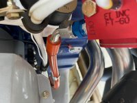
FT-60 Red Cube Relocation for -14A with EXP119

1949MGTC

Active Member
Sponsor
My FT-60 Red Cube failed after 15 hours on my -14A with an EXP119. I worked with Aircraft Specialty to develop a new kit to relocate the FT-60 from the engine intakes to the engine mount. This new solution has produced much smoother fuel flow data and extremely accurate flow rates. If you are interested in the alternate location for the FT-60 Aircraft Specialty now has kits available. I've attached some photos for review.

Regards,
Bill Gardner
N513DB
SN 140849
 

Attachments

  • IMG_5922.jpg
    IMG_5922.jpg
    595 KB · Views: 425
  • IMG_5923.jpg
    IMG_5923.jpg
    529.4 KB · Views: 292
  • IMG_5925.jpg
    IMG_5925.jpg
    629.7 KB · Views: 313
  • IMG_5926.jpg
    IMG_5926.jpg
    834.6 KB · Views: 297
  • IMG_5927.jpg
    IMG_5927.jpg
    568.3 KB · Views: 299
I like it. I’m guessing that this might also work for non- exp engines. Never have liked that red cube on the intake tubes. Thanks for sharing the quality
pics !
 
I think the non-EXP engines have a different fuel injector unit, so I'm not sure if the length of the forward hose would work. I would contact Steve at Aircraft Specialty and you can help him develop a solution for the non-EXP engines! I think the rest of the setup would work though.

Bill
 
Bill and all---since this package uses 2 hoses, supply and discharge, the supply hose could be the same for most all installations. The discharge hose might obviously be custom to fit whatever sump/servo combination.
With that in mind, its a fairly 'universal' install.

Tom
 
Tom,

Do you think this kit would work on an RV-7A? I have a similar setup but my red cube in on the firewall and I am having some very inaccurate readings (reading high at altitude).. I just don't want to spend 300+ bucks just to find out FF isn't accurate..
 
Certainly Randomir----its pretty universal for most FWF applications. Doesnt matter if you hve a vertical induction, or horizontal. Only change would be the outlet hose from the transducer to the servo. I think where would be 3 dfferent possibilities for that one.

Tom
 
Mine has horizontal (it's an angle valve 360).. and currently it's a straight fitting just like pictured here (though my servo is different - not this gold color one) but supply into it looks pretty much same (straight fitting on the side).

Does AS have any return policy? What if this 14A kit doesn't work for me for some reason? (I have an oil cooler on the firewall that may potentially get in the way at least some.. though I am somewhat confident this setup would have enough clearance..

PS. Do you know what the lead time is for the kit? I would order today if there's enough confidence it'd work in my config
 
Return policy is if you arent happy with the quality of our product then certainly return it for a refund. We do alot of preliminary work to make sure it things work in your application.
NO---we dont guarrantee the transducer will read correctly, but we do guarrantee that our hoses will flow. Since we dont do the install, its up to the builder to verify his install is satisfactory.

WE do alot of independent beta testing, as Bill did on this package. Its easy to do an install when you have dont the design and the mockups alot. But get an actual client to do it, and you may find something you hadnt considered.

Tom
 
Thanks Tom.. I'll give it a try and see how it works.. just ordered, so hopefully it ships soon.. I have some time next week to play with it :)
 
I'll post an update - received the kit.. very nice and clean install.. was not hard to do at all.

Now, the bad news -- it did not fix the issue. Still reading wrong above about 5,000ft... no matter what.. fully leaned out at 9500ft it's reading 9.6gph (actual burn is right around 7-7.5 or so..).. I noticed that pulling back the throttle just a little bit (backing off WOT) seemed to "help" somewhat... so not sure which "side" is causing issue here..

Several folks had this same issue and doing this type of install (on engine mount, pointing "up" a bit) seemed to help them.. but no luck here..

Anyone got ideas?

Yep - identical problem on an RV-14A I worked on. The flow meter went to a higher than actual readout at ~5K’ regardless of mixture or power settings. The cube was mounted on the engine per the Van’s plans.

Moving the cube to the engine mount solved the problem. I mounted the cube in my RV-8 in a similar fashion. It works perfectly.

Carl
IMG-0679.jpg
 
I mounted mine on the engine mount just behind the number four cylinder. After reviewing another discussion on this platform, it was my understanding that this would be the best option for the cube. Other builders at my location have since looked at my install and all agree.
 
Carl, I had found your post earlier and was more or less following the same idea using this neat RV-14A kit that these guys sell.. so it was very easy to try out.. but no luck..

I am out of ideas what to try next.. trying not to randomly throw money at this..
 
Tom, the kit from AS did not "work" in my case.. nice kit but FF reading very wrong still - same as before using the kit.. relocating the sender made no difference.. and it's quite a different setup from before..
 
I believe I’ve got the same problem- I’ve only 30 hours on the aircraft and only a couple of flights above 5000’ but on those occasions I’ve seen an indicated 38 litres per hour fully leaned at 8000’ as opposed to about 32 litres at a lower level.
The FT-60 is fitted as per plans. I’ll do a few more investigative flights to confirm but the question is - do I relocate the red cube with a $320 AS kit or replace the red cube itself?- or possibly both costing a half AMU!


Ian.
RV14A EI-XIV.

I had the same problem as you and others; above 5000' and the FF reads far higher than it should. I replaced my red cube, which did not solve the problem. I have not relocated the cube, and may not since it doesn't seem to be a fix for everyone who has this problem. FF is accurate below 5000'.

-Alex
 
Radomir---its not our KIT--which only provides the hoses for the location. It has nothing to do with the operation of the transducer. If the engine runs, it's getting fuel, and thats what our hoses provide. So saying our kit 'didnt work' is not correct, it works just fine, but the transducer has an issue. Whether it's an internal problem, a wiring problem, an engine ground problem, or the EFIS translation of the signals from the transducer, thats not up to us. That would be between the installer and EI.

I know this for sure: We've designed a bunch of different install packages to put the transducer in different locations for builders. In every case, IF there was a reading anomaly, it was due to an actual transducer issue, but much more common was the wiring installation. You can have several installs in the exact location, with the same hose packages, and you may have a reading variance. Why? gee if I had that answer it would be fabulous.

But your issue is not the hoses. So ====WE stand by our policy, if you arent happy with the kit, return it for a refund.

Tom
 
Tom, the kit from AS did not "work" in my case.. nice kit but FF reading very wrong still - same as before using the kit.. relocating the sender made no difference.. and it's quite a different setup from before..


Try a new red cube. I’m convinced the stock engine location beats the transducer into a failure state. I watched my flow data get more erroneous over about 15 hours before I changed locations and red cubes.

Bill
 
A theory...

There have been countless reports of Red Cube (EI FT-60) failures, inaccuracy, and only a very few root causes of the failure explained (i.e. teflon tape became dislodged from NPT thread and wrapped itself around the wheel...)

The EI installation guide describes very few limitations; wires up, output higher than the input, downstream of the last pump. We've inferred way too many other things -- to the point that the Red Cube needs to be mounted on a pole outside of the aircraft and maintain a constant orientation (sort of like a Garmin GTN antenna ;) )

However, this caught my eye -- from the EI data sheet -- https://iflyei.com/wp-content/uploads/FT-60-Info-Rev-F.pdf:

Electrical Interface:
The Red Cube FT-60 interfaces with the FP-5(L) and most other fuel flow instruments. The input (red power lead)
will operate from 8 to 30 Volts. Typical supply current is 14 mA over the entire operating range. Power to the FT-60
should be regulated and supplied by the instrument interfacing with the FT-60.
The FT-60 incorporates an open collector output (white lead). The output can operate from 0 to 30 Volts. Saturation
voltage at a given sink current is 0.25 Volts (typical) at 4 mA and 0.7 Volts (max) at 10 mA. The output should be
limited to 15 mA max. Recommended pull-up current is 1 mA. The output incorporates a two-stage comparator that
keeps the output waveform square, even at low flow rates.


I have a theory -> Is it possible that these inaccuracies have nothing to do with hose routing, heat, or location along the fuel stream. Rather, could they be related to the cleanliness of the DC supply going to the Red Cube?

An easy way to prove this theory would be to turn OFF the alternator in flight, power the airplane solely from the primary/secondary battery and observe the fuel flow data -- did it stabilize? report accurately?

Again, just a theory...
 
I can try out your theory on my next flight but why is the reading affected by altitude- correct below approximately 5000’ and incorrect above?


Ian
RV14A EI-XIV.
 
"I have a theory -> Is it possible that these inaccuracies have nothing to do with hose routing, heat, or location along the fuel stream. Rather, could they be related to the cleanliness of the DC supply going to the Red Cube?"

Certainly. As I stated earlier, and there are a LOT of threads on this subject, Location, within reason, has little to do with the readings. Of course, if the location inhibits the fuel flow, or the wires are subjected to strain or high heat, then yes location can be a cause for failure. All of the anomalies have appeared to be electrical in nature, but what that it is I dont know. We thought we had it narrowed down to a particular avionics manufacturer and their interface with the transdcuer, but that theory got discounted after indepth research.

Perhaps some of you electrical gurus can come up with a solution.

Tom
 
SNIP

I have a theory -> Is it possible that these inaccuracies have nothing to do with hose routing, heat, or location along the fuel stream. Rather, could they be related to the cleanliness of the DC supply going to the Red Cube?

I suspect not. Remember the common issue is this happens at altitude, typically starting at 5k’. My theory is the combination of:
- How the cube is mounted
- Length of hose from the mechanical fuel pump to the cube
- Length of hose from the cube to the FM
- The use of 90 degree fittings on the cube, inlet or outlet
- Engine vibration
- Atmospheric pressure
Will cause some sort of resonance at the little wheel in the cube causing the problem.

As has been shown in this thread, this is not a one off. Don’t waste your money replacing the cube as this does not fix the problem.

I suggest:
- Mount the cube per the instructions that came with it. For RV-14 people this translates to NOT mounting it on the engine like Van’s instructions tell you.
- If you mount it like I showed in my last post and you still have a problem then change something. Here a longer hose added at the inlet or outlet, a different spot on the engine mount, etc.
- One approach that seems to work well is to mount the cube vertically between the FM and spider. Here the cube would be suspended via the inlet and outlet hoses - not hard mounted to the engine.

Carl
 
I can try out your theory on my next flight but why is the reading affected by altitude- correct below approximately 5000’ and incorrect above?


Ian
RV14A EI-XIV.

Is the RPM different? Electrical configuration different - more/less load at different altitudes (eg. lights on/off)…

Just thinking outloud.
 
For fun, here is my "original" configuration plus first attempt to fix:

https://ibb.co/1b5NdTS


Originally, the outlet (at top) had a sharp 90-degree AN elbow fitting.. What is pictured here is me trying to smooth it out with red-colored fitting. It made no difference (possibly, made it slightly worse but it was one test flight so no hard conclusions).

Second attempt was using this -14 hose kit to relocate the transducer. so currently have it mounted on engine mount, just as shown in pictures at beginning of this thread.. quite a different setup, yet identical results!!

Also noted on last flight (with current config) is that backing off throttle just a bit (dropping maybe 0.2" off WOT at 8500ft dropped FF reading by no less than 1gph - and that seemed like a big drop to me.. is the plate inducing some "turbulence" that affects the reading?). I need to test this a bit more, though.. good excuse to go flying today.


I am not discounting any theory yet, but electrical one sounds weird that it'd be altitude dependent..
 
Another data point

300+ hours on stock -390 per Van's installation instructions. Accurate to within 0.1-0.2 gal every fill up.

On second thought I DID add an extra heat shield and wrapped with fire barrier, other than that completely stock
 
300+ hours on stock -390 per Van's installation instructions. Accurate to within 0.1-0.2 gal every fill up.

On second thought I DID add an extra heat shield and wrapped with fire barrier, other than that completely stock

Same here -- with a couple of exceptions:

1. Additional heat shield positioned along the #2 exhaust header.
2. AN4 hardware instead of the MS24694-S72 screws. Required upsizing the the holes in the MS21919-WCH26 clamps.
3. Additional AN960 washers between the bottom of the red cube and the MS21919 clamps.
3. Used AN816-6 (steel) fittings on the input and output, no 45° elbow.

>sigh<
 
I suspect not. Remember the common issue is this happens at altitude, typically starting at 5k’. My theory is the combination of:
- How the cube is mounted
- Length of hose from the mechanical fuel pump to the cube
- Length of hose from the cube to the FM
- The use of 90 degree fittings on the cube, inlet or outlet
- Engine vibration
- Atmospheric pressure
Will cause some sort of resonance at the little wheel in the cube causing the problem.

As has been shown in this thread, this is not a one off. Don’t waste your money replacing the cube as this does not fix the problem.

I suggest:
- Mount the cube per the instructions that came with it. For RV-14 people this translates to NOT mounting it on the engine like Van’s instructions tell you.
- If you mount it like I showed in my last post and you still have a problem then change something. Here a longer hose added at the inlet or outlet, a different spot on the engine mount, etc.
- One approach that seems to work well is to mount the cube vertically between the FM and spider. Here the cube would be suspended via the inlet and outlet hoses - not hard mounted to the engine.

Carl

Attached for reference.

https://iflyei.com/wp-content/uploads/EI-FT-60.pdf

The only divergence from the RV-14(A) plans that I can see is the phrase -- "This transducer must be suspended between flexable (sic) hoses on the inlet and exiting ports."

My inference from this, is that the mounting should be changed from the body of the transducer to the fuel lines -- allowing the red cube to "float."

Brian
 
Also noted on last flight (with current config) is that backing off throttle just a bit (dropping maybe 0.2" off WOT at 8500ft dropped FF reading by no less than 1gph - and that seemed like a big drop to me

I believe the first throttle movement off WOT turns off the enrichment mechanism on the servo and the large initial drop is to be expected. I drop from >19 gph to 15 gph with the first 1/4 to 1/2 inch.
 
So--the big question is why does it work fine on some planes but not on others with the same install?
One on the great mysteries of our time.
Tom
 
Put a scope on it

For anybody who has this problem, if you can get hold of a portable oscilloscope or a laptop plus a cheap USB DAQ card, you'll probably see something interesting in the data. You'd have to break into the signal wire to route it to the scope but I suspect you'll see something funky in the waveform when the problem occurs. I've used this technique to troubleshoot turbine type flowmeters successfully in ground test equipment, usually due to EMI/shielding issues. I also used it to find a broken tooth in the differential ring gear in my truck. At 60 mph, my ABS light would come on and when I hooked it up to an oscilloscope, I could see the shape of the waveform change around 60 mph, just enough apparently to make the ECU mad.

For the red cube, if you disconnect the output wire going to the avionics, you'll need to add an external 2.2k or higher pullup resistor to +14 since it has an open collector output.

-Bob
 
So--the big question is why does it work fine on some planes but not on others with the same install?
One on the great mysteries of our time.
Tom

Tom are your fuel hose kits before and after the red cube the same on the 14 & 14A? I have a 14 that works just fine and a friend with a 14A that has the 5000' accuracy issue. We both purchased your hose kits and installed according to Van's plans. Both engines are non-EXP.
 
Last edited:
If it is a function of altitude, then my guess would be cavitation. It's probably on the ragged edge for most people and a particular installation where there might be slightly higher pressure drop upstream of the flowmeter due to an extra bend, sharp 90 deg, etc. would tend to make it show up more often. Couple that with fuel that may be on the edge of the vapor pressure spec and cavitation would show up. Assuming the flowmeter is downstream of the electric boost pump, if you turn the boost pump on and the issue disappears, then it is probably cavitation and the only way to fix that is for fewer bends/elbows in the lines upstream. Flowmeters are also really sensitive to flow conditioning upstream and downstream so ideally you want 10-20 diameters of straight section before and after. That's hard to get in a FWF install so if you turn on the boost pump and it doesn't go away, insufficient flow conditioning might be the problem. I haven't started on the FWF section of my -10 yet but I may look for some inline flow straightners that would help (although at a risk of increased pressure drop). It could also be some sort of strange resonance that only shows up at the power settings and cooling airflow (acoustic resonance) typically encountered at 5000 feet and above. And it could be all of the above showing up at different times.

Attached are some pages from the Flow Technology Turbine Flowmeters manual.

-Bob
 

Attachments

  • troubleshooting1.png
    troubleshooting1.png
    218 KB · Views: 30
  • troubleshooting2.png
    troubleshooting2.png
    201 KB · Views: 22
  • troubleshooting3.png
    troubleshooting3.png
    156.8 KB · Views: 17
  • troubleshooting4.png
    troubleshooting4.png
    95.1 KB · Views: 14
  • troubleshooting5.png
    troubleshooting5.png
    166.7 KB · Views: 16
  • troubleshooting6.png
    troubleshooting6.png
    57.8 KB · Views: 19
Last edited:
Glen---pretty much. VERY minor change to the inlet hose to the transducer to make a slightly better routing.

The strange thing about all of this is that some planes are just fine, and some arent, but have the same plumbing and locations. I'll bet that you could put 5 equal model planes on line, and you would have 1 that would have some anomalous readings. Yall are saying 5000 feet? Hum, thats weird.

Tom
 
Algorithms?

One more thing -- all things being equal, at least from a plumbing perspective...

In my last RV-7, I used a Red Cube connected to AFS 3400EM. It was ->rock solid< and accurate to within ~2% ( 1 gallon on 42 total ).
https://apps.savvyaviation.com/flights/shared/flight/3438640/e350604d-25af-4c62-9ebf-22119e465eb9

Current RV-7, same Red Cube - Garmin G3X Touch/GEA 24, same location, plumbing, mounting and engine as before, and it's not solid or as accurate (~7% -- 3 gallons on 42 total ).
https://apps.savvyaviation.com/flights/shared/flight/7564031/6441ae5a-2f08-4c91-b59c-27747d304f00

What's different? The algorithms deployed to measure the pulses from the Red Cube (Rob Hickman is a coding genius -ed). Zoom in to see how much wiggle is there in the data.

It would be interesting to see how the other EFIS/EIS behave when connected to the Red Cube. Dynon? AFS? GRT? MGL? JPI? Anyone?


B
 
Last edited:
That's an interesting point. My G3X MAP, FF, etc seems pretty sensitive. Thus said my FF seems much more accurate than 7% deviation. As I've said, I've never been more than .3 off on a 32-35 gallon fill up. That's also assuming the fuel pump has zero margin of error.
 
What's different? The algorithms deployed to measure the pulses from the Red Cube (Rob Hickman is a coding genius -ed). Zoom in to see how much wiggle is there in the data.

It would be interesting to see how the other EFIS/EIS behave when connected to the Red Cube. Dynon? AFS? GRT? MGL? JPI? Anyone?


B

I'm replacing a burnt out Floscan 201 (previous owner connected it to 24v and fried it) with a red cube today. I'm connecting it to the MGL Extreme EMS so we'll see what it does on mine.
 
Brian, now that I think about it, its does seem that the Dynon and Garmin EFIS systems seem to be sensitive. I dont recall the MGL having the issues, but I also dont recall anywhere as many MGL systems.

I'm not one of you electrical gurus, but is there a setup page that can dampen the sensitivity of the flow transducer signal? Gee would that be great.

Tom
 
My installation went peachy and I now have fuel flow. I installed it per the factory instructions so it's wired correctly and

- attached by the hoses 4" from each end of the cube, with the cube floating,
- AN816-6 steel straight fittings on both ends to both hoses,
- after engine fuel pump and before the FI servo,
- wires pointing UP,
- OUT sitting higher than IN so bubbles escape,
- wrapped in Fire Hose to keep it cool,
- and I dialed in the K Factor (easier than the FloScan & it's $152 cheaper too).

No leaks during the engine test run so my only question I'll be asking the MGL folks is : what's the sample rate? It seems that it reads & changes the display every +/- 4 seconds. It might be that it's not reading it correctly or that I have to change some setting so we'll find out soon enough.
 
Thanks to Charlie Rodz for sharing this off thread - there is a looooong thread on another engine forum that goes on about their issues with fuel flow accuracy; in a nutshell, putting a dedicated/isolated DC-DC supply on the transducer seems to have resolved their issues.

What bothers me about this “theory” is the Garmin, and Dynon have their own DC-DC regulated supply for all of their transducers. Or do they ? Maybe G3xpert can confirm…

Next step, make a DC-DC supply and see how it works…

Tom - there isn’t a setting for this in the Garmin stuff… :(
 
Thanks for the update Brian.
Hum kinda verifies the install package design, I think.
Isnt it strange that some planes have the problem and others dont. Power and grounds do matter.

Tom
 
As a general point of reference, there are different versions of the RV14A EXP119 FWF red cube hose setup. There is the "stock" installation and the very new "relocation" version. The stock install is what we have traditionally been using and what we provide to VANS for their OEM FWF hose packages.

The relocation kit ONLY came about as a result of builders requesting to move the red cube to a different location to attempt to avoid the heat in the standard location. As an ancillary benefit, relocating appears to have smoothed out the data in beta test aircraft.

As has been discussed, there are a lot of variables at play with these red cubes, and lots of different data points. If the red cube is located in the stock location and everything is running nicely, there is likely not a benefit to relocate it. For builders that are having issues or failures that may be attributable to heat/vibration, this is one option that may be available.

Or, a third option is if you want to design something completely different from a relocation standpoint, we are always happy to build custom hose assemblies to accommodate that.

If the red cube is providing erroneous data regardless of how it is plumbed or where it is located, then it would seem that something else is likely the culprit.
 
Last edited:
As a general point of reference, there are different versions of the RV14 FWF red cube hose setup. There is the "stock" installation and the very new "relocation" version. The stock install is what we have traditionally been using and what we provide to VANS for their OEM FWF hose packages.

The relocation kit ONLY came about as a result of builders requesting to move the red cube to a different location to attempt to avoid the heat in the standard location. As an ancillary benefit, relocating appears to have smoothed out the data in beta test aircraft.

As has been discussed, there are a lot of variables at play with these red cubes, and lots of different data points. If the red cube is located in the stock location and everything is running nicely, there is likely not a benefit to relocate it. For builders that are having issues or failures that may be attributable to heat/vibration, this is one option that may be available.

Or, a third option is if you want to design something completely different from a relocation standpoint, we are always happy to build custom hose assemblies to accommodate that.

If the red cube is providing erroneous data regardless of how it is plumbed or where it is located, then it would seem that something else is likely the culprit.

Steve, could I use the "relocation" hoses, which were made for the -14, in my -14A? Thanks,
Alex
 
Steve, could I use the "relocation" hoses, which were made for the -14, in my -14A? Thanks,
Alex

Yes, they were beta tested on a 14A with the EXP119 engine.

We have another beta test coming up in the next few months on a 14A with the NON exp engine.

Haven't received an inquiry yet for someone wanting to test it on a 14TW. However, we are happy to try that out too when we have a 14TW owner wanting to do it.

Many of our new projects are a result of requests from builders/owners who are looking to tweak the mousetrap a little bit.

Steve
 
Haven't received an inquiry yet for someone wanting to test it on a 14TW. However, we are happy to try that out too when we have a 14TW owner wanting to do it.

Hey Steve.
I’m Interested. Have a 14TW in process. Willing to Try new things.
 
Hi all,

I noticed one thing about many of these installs including the relocation kit from Steve. The install instructions for the cube call out to avoid a downward slope on the hose exiting the cube. It can induce cavitation in the cube near the turbine.

You might consider locating the cube lower by attaching it to the bottom of the adel clamps instead of the top. I haven't tested mine yet, but I think this has a good chance of helping those with inconsistent readings.

Regards,
G
 

Attachments

  • PXL_20231126_183238709.MP.jpg
    PXL_20231126_183238709.MP.jpg
    202.3 KB · Views: 76
J.P. Instruments installation instructions

J.P. Instruments has a similar unit (probably with less electrical noise immunity due to higher impedance) that has similar installation instructions, look under the Specifications tab. Here's an excerpt:

"Install Overview:

Make sure the transducer is Horizontal with the three wires up. Failure to do this will result in premature failure. Please refer to Report #503 that came with your EDM with Fuel Flow.

Mount in a horizontal position with the wires up, as this ensures that the rotor is in proper orientation to the flow of fuel just as it was calibrated.

Be sure there is no bend in the line closer than 6 inches before or after the transducer. Do not use aluminum fittings when installing the fuel flow transducer.

For carbureted engines, before the carburetor. If the transducer is higher than the carburetor, put an anti-siphon loop in the line that peaks higher than the transducer (see installation manual, but the diagram shows the transducer on its side, rather than the correct position which is with the wires coming off the top).

For injected engines, between the engine fuel pump and the servo regulator. For injected engines with vapor return lines (rare), between the servo regulator and the flow divider (spider).

Mounting the transducer between the electric boost pump and the mechanical pump is not recommended.

Do not hard mount the transducer to the engine. Vibration may damage the internal parts of the transducer or cause erratic readings."

Here's how they describe their unit:

"Here’s how it works in an aircraft; liquid enters through one side and enters the flow chamber. It follows a helical flow path, and exits vertically, thereby venting vapor bubbles that might form during the fuel flow. As the liquid flows, it has a velocity that can be measured and this velocity is directly proportional to flow rate.

Inside the fuel flow transducer, is a miniature neutrally buoyant rotor finely balanced on jeweled bearings. As the fuel flows past the arms of the rotor, it pushes against the arms of the rotor and so, the rotor begins to spin.

Now, on one side of the spinning rotor is an infrared light emitter while on the other side, is an infrared light detector. As the arms of the rotor spin, it interrupts an infrared light and this constant on-off is calculated to arrive at the spin rate and therefore, the fuel flow rate. Ingenious, simple and fool proof.

JPI FF transducers use a more sensitive but rugged version of a typical fuel flow transducer, suitable for a wide range of aircraft use."

Sounds pretty similar to the Red Cube.
 
J.P. Instruments has a similar unit (probably with less electrical noise immunity due to higher impedance) that has similar installation instructions,

Sounds pretty similar to the Red Cube.

JPI uses a Floscan 201a-6, that's what's in your link. The Red Cube is a lot cheaper and after working with both this week I like the Red Cube more, don't know why, maybe because it's working and the other one wasn't? :D

The Floscan is only for 12v systems and the Red Cube (FT-60) is for both 12v and 24v systems.

The Red Cube is also cheaper by over $150 !
 
Back
Top