What's new
Van's Air Force

Don't miss anything! Register now for full access to the definitive RV support community.

EFI Fuel Pump Failure Risk

How do you use your fuel pumps?

  • SDS System: 1 Pump on for TO

    Votes: 6 14.3%
  • SDS System: 2 pumps on for TO

    Votes: 18 42.9%
  • EFII System & Bus Manager: 1 pump on for TO

    Votes: 11 26.2%
  • EFII System & Bus Manager: 2 pumps on for TO

    Votes: 1 2.4%
  • EFII System NO bus manager: 1 pump on for TO

    Votes: 3 7.1%
  • EFII System NO bus manager: 2 pumps on for TO

    Votes: 3 7.1%

  • Total voters
    42
Is this why FP varies along with the MP?

Like Matt showed earlier, I too noticed that the FP varies with the MP.
Then it got me thinking, as Dan says, why??

I understand Ross' explanation to the FPR being overwhelmed and not "opening" enough when 2 pumps are working.

I have 1 pump working at a time.
I measured my (free) flow to be 50 USG/hour.

At startup, engine not running, I have 35.6 PSI
Aeromotive FPR
Fuel Pressure Sensor connected to Regulator.

The pump just pumps... it pressurizes the rail, doesn't care how much fuel the injectors take.
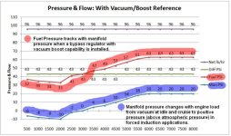
When the fuel demand is high, the regulator keeps the pressure up by "closing" thus less flow to the return line??
When it's low, the regulator "opens" allowing the surplus pressure to flow more freely to the return line??

Does the pressure in the rail stay more or less the same at high or low power??

Is the varying FP shown on our instruments due to the physical placement of that fuel pressure line to the sensor when the regulator is moving more or less fuel to the return line??

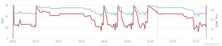
At 29,5 MP = 34,6 PSI FP
At 6,1 MP = 23,5 PSI FP
 

Attachments

  • Capture d’écran, le 2023-05-08 aÌ€ 13.49.11.jpg
    Capture d’écran, le 2023-05-08 aÌ€ 13.49.11.jpg
    53.1 KB · Views: 51
..lTurned out there doesn't seem to be any hard data relating return capacity to rail pressure...and folks are using both -4 and -6.

This intrigued me so I went and looked at my install manual and my installation. The SDSEFI Installation Manual recommends -6 fuel line for both delivery and return lines, I complied with that recommendation.

While I was typing, Ross responded with his memory of my set up and he has a very good memory. My system was one of the originals for the IO-390 and it needed a little adjusting to work. Originally I was using 25ish PSI of fuel pressure. To set the RPM/AFR map one tweaks the fuel flow parameters from 0 to 255 to get the desired AFR from the O2 sensor. I was nearly always at 255 and still too lean. Ross suggested I increase the fuel pressure. I now run 50PSI and my engine gets the AFRs needed.

My understanding is the newer versions have a different atmospheric table and they may be able to run lower fuel pressures. I suspect I could get those tables from SDS, but I’m more than content with how my engine operates. Like I typed earlier, I removed the O2 sensor many year ago because everything just works and I can get the info I need from a standard EGT indication.

In summary, -6 fuel lines, Borla regulator, and higher fuel pressure may be why I’ve not noticed the over rich situation. Learning has occurred :).
 
Last edited:
Like Matt showed earlier, I too noticed that the FP varies with the MP.
Then it got me thinking, as Dan says, why??

For my set-up the fuel pressure changes with mp because of the 1:1 boost ratio. I assumed the Bora the same design. That is how I knew my FPR was damaged as it would not track the boost correctly.
 
Last edited:
Like Matt showed earlier, I too noticed that the FP varies with the MP.

Note "vary with MP" and "vary between one or two pumps" are different questions.

Does the pressure in the rail stay more or less the same at high or low power??

That's the theory. To understand your numbers, convert MP to PSI.

29.5"hg is 14.5 psi
6.1" hg is 3 psi

Now you have

34.6 - 14.5 = 20.1
23.5 - 3 = 20.5
 
Was this flow rate measured before or after the FPR? Walbro GSL393? Sounds a tad on the high side for the 393 at 35.6 psi. Thanks
No FPR, this was free flowing out of the pump to a 20 litre gas can.
Filled it in 6 minutes.
20 litres X 10 = 200 litres /hour (+/- 50 USG/hour)
 
393 Performance curve

No FPR, this was free flowing out of the pump to a 20 litre gas can.
Filled it in 6 minutes.
20 litres X 10 = 200 litres /hour (+/- 50 USG/hour)

This is pretty close to the Walbro performance curve prediction. (54 gals at 0 psi and 13.5 volts) Of course you probably had more than zero pressure (AN6 hose back pressure adds something) and I am not sure if Walbro used a flooded suction but close to the same numbers I was getting before the FPR.

Thanks
 
Like Matt showed earlier, I too noticed that the FP varies with the MP.
Then it got me thinking, as Dan says, why??

For my set-up the fuel pressure changes with mp because of the 1:1 boost ratio. I assumed the Bora the same design. That is how I knew my FPR was damaged as it would not track the boost correctly.

On mine, yes the Borla tracks the MP and adds that to the FP, 1:1. Are there other regs out there (in use with SDS) that don't?

FWIW, a new player in the EFI market is incorporating a pressure sensor, the output of which is used to modify injector open time with variation of rail pressure...closed loop compensation.

That's very interesting - but would tend to cover up a clogging final filter, I would want to see a limit to how far it could adjust without an alert to the user, or a fuel pressure alarm if it goes out of certain limits.

Ross - can you insert a user-settable "fuel pressure window" to be acceptable and alarm outside that window in your software? I've already got that in my Dynon of course, but not everyone has a Nanny EFIS in the plane. Can you pick up the fuel pressure reading from a shared sensor or pick it out of a data stream from the EFIS, to avoid duplicate sensors?
 
Last edited:
This is pretty close to the Walbro performance curve prediction. (54 gals at 0 psi and 13.5 volts) Of course you probably had more than zero pressure (AN6 hose back pressure adds something) and I am not sure if Walbro used a flooded suction but close to the same numbers I was getting before the FPR.

Thanks
Yes and might I add that I "measured" 20 litres by eye, against the embossed line on the jerrycan and stopped the clock.
I've seen more accurate in experiments...
So 50 is a rough figure, close enough but not as accurate as the Walbro curve prediction
 
Ross - can you insert a user-settable "fuel pressure window" to be acceptable and alarm outside that window in your software? I've already got that in my Dynon of course, but not everyone has a Nanny EFIS in the plane. Can you pick up the fuel pressure reading from a shared sensor or pick it out of a data stream from the EFIS, to avoid duplicate sensors?

A simple thing that people can do to detect a clogging downstream filter is to tap fuel pressure off before the downstream filter. If nominal is 45 psi, and you start seeing that rising, that filter is probably plugging. It won't tell you much about upstream filter condition though. We have seen downstream plugged but not upstream- strange as that sounds.

I've been flying with two rather small filters for about 20 years and never had any problems or significant fines in them on inspection. I burned 100LL for the first decade and mogas for the last. I'm not sure why some others are seeing serious accumulation in a short time span. We are not sure where the contaminants are coming from unfortunately and they may be different in different aircraft.

In future, we'll be able to do some other wonderful things with comm between boards and other devices, just not enough time to get all of that done and tested for this software release right now.

We have too many ideas and not enough time...
 
Last edited:
So one of the basics for most EFI systems is that fuel pressure is ideally maintained at a constant differential over MAP. You'll see that FP drops at idle by about 10 psi from static (engine not running). This is in response to only seeing about 10 inches MAP vs. 30 inches with engine off or at WOT at sea level.

On a boosted engine, FP will rise proportionally too as MAP rises above 30 inches so that there is always 45 psi effective differential across the injector.

About 2 inches hg = 1 psi for rough calcs.

As I stated before, flow varies as the square root of the pressure increase. So if you double pressure, you get about 1.41 X the flow. This excludes the dynamic changes in injector characteristics (opening and closing rates). That's another subject, but within the usual range of most EFI injectors (roughly 30-60 psi), things remain fairly predictable.
 
Filter clogging

A simple thing that people can do to detect a clogging downstream filter is to tap fuel pressure off before the downstream filter. If nominal is 45 psi, and you start seeing that rising, that filter is probably plugging. It won't tell you much about upstream filter condition. We have seen downstream plugged but not upstream- strange as that sounds.

In future, we'll be able to do some other wonderful things with comm between boards and other devices, just not enough time to get all of that done and tested for this software release right now.

We have too many ideas and not enough time...

Ross is correct I think the only way to detect a downstream clogged filter early clogging is to install a tap BEFORE the post filter. EVENTUALLY the pressure will fall (In the current pressure gauge location) as the filter gets very clogged and the engine is trying to consume more than the filter will pass but this means the filter is only capable of passing say 10 GPM vs the ~ 35 GPM it was originally passing. During the filter clogging from 35 GPM to 10 GPM the FPR will cover up this issue.

Below is a chart I found years ago when I was trying to troubleshoot my FPR failure. Shows the effect of a 1:1 boost and ensuring the units are correct is import. 14.7 psi approx. 29.92 in Hg. Note constant delta to obtain higher FP's.
 

Attachments

  • boost table.jpg
    boost table.jpg
    74.3 KB · Views: 41
re: pressure sensing and filter clogging - yes, agreed.

I am currently sensing post-filter and know that my system runs at a constant 44 psi under (single-pump) almost all conditions. When it decays through 43 into 42, I know it's time to clean the filter. The same could be done with a prefilter pressure sensor, watching it climb above 44 through 45 into 46, but the key takeaway is the same - know your system and look for trends away from nominal.
 
Note "vary with MP" and "vary between one or two pumps" are different questions.


That's the theory. To understand your numbers, convert MP to PSI.

29.5"hg is 14.5 psi
6.1" hg is 3 psi

Now you have

34.6 - 14.5 = 20.1
23.5 - 3 = 20.5
Thanks Dan,
Yes, I get that they are 2 different situations, 2 pumps vs. 1 pump = different FP. As in the OP's initial question, 1 or 2 pumps on takeoff.

VS. my observation/question relating to the fuel pressure (measured from the regulator) varying along with MP.
Instinctively, my first thought would be that the FP (in the fuel rail) stays closer to a fixed value throughout the flight independant of the throttle's position. But I (or most of us?) don't have a FP sensor on the rail or spider.

I'd like to understand how both relate.

Substracting the manifold air pressure from the fuel pressure?
FP (34,6 psi) at WOT on takeoff (14,5 psi) = a delta of 20,1 (high RPM)
FP (23,5 psi at closed throttle (3 psi) = a delta of 20,5 (low RPM)
Very close numbers, ok is there a reason or is it a coincidence?

Does high or low RPM influence the data as the FF changes? Will have to check that on another flight: same MP, varying RPM vs FP...

Additional data according to my graph:
FP (32,9 psi) at cruise MP of 22,3 inHg (10,9 psi) = a delta of 22 (med RPM)
FP (29,1 psi) reducing speed on downwind MP 16,6 inHg (8,2 psi) = 20,9 (high RPM)
Again, pretty close...
Why? Because the sensor is connected to the regulator and...???
Thanks for any explanation, understanding the why is bliss !!
 
So one of the basics for most EFI systems is that fuel pressure is ideally maintained at a constant differential over MAP. You'll see that FP drops at idle by about 10 psi from static (engine not running). This is in response to only seeing about 10 inches MAP vs. 30 inches with engine off or at WOT at sea level.

On a boosted engine, FP will rise proportionally too as MAP rises above 30 inches so that there is always 45 psi effective differential across the injector.

About 2 inches hg = 1 psi for rough calcs.

As I stated before, flow varies as the square root of the pressure increase. So if you double pressure, you get about 1.41 X the flow. This excludes the dynamic changes in injector characteristics (opening and closing rates). That's another subject, but within the usual range of most EFI injectors (roughly 30-60 psi), things remain fairly predictable.
While I was writing my last post, Ross put this out, thanks.
OK, so constant delta between FP and MP is a good thing. Why?

Is it an easy explanation?

How is it done, with the regulator being connected to the MP??

Makes me consider adding a FP sensor post filter as Greg did to monitor an eventual clogging.
 
Last edited:
While I was writing my last post, Ross put this out, thanks.
OK, so constant delta between FP and MP is a good thing. Why?

Is it an easy explanation?

How is it done, with the regulator being connected to the MP??

Makes me consider adding a FP sensor post filter as Greg did to monitor an eventual clogging.

If I’m understanding your question, yes, the FP regulator has a MP vacuum line connected to it…that’s the only way it can “regulate” the fuel pressure. The engine produces more vacuum when idling and the vacuum decreases as the RPM’s increase. So, with the engine idling and not needing much fuel, the FP regulator is open, which allows most of the fuel to be returned. Then, as the engine increases in RPM’s, it produces less and less vacuum which in turn allows the regulator to close more and more so that less fuel is allowed to pass through it and more fuel is supplied to the engine. So MP controls the regulator and is a direct relation to the amount of fuel the engine needs.

Regarding placement of the fuel pressure sender, the best place to put it so as to monitor the health of the post pump filter, is to place it “pre” filter (between the pump and the filter). In doing it this way, if you were to notice your fuel pressure starting to go up, this would be an indication that your post-pump filter needs cleaning or replaced.
 
OK, so constant delta between FP and MP is a good thing. Why?

Given a injector's known flow rate at a known pressure, a specific quantity of fuel can be injected by calculating the length of time to hold its pintle open. A change of differential pressure (fuel pressure on one side, manifold pressure on the other) alters the flow rate, which makes the time calculation inaccurate.

How is it done, with the regulator being connected to the MP??

Manifold pressure is piped to a chamber above the regulator's diaphragm while pump pressure is applied to the bottom side. A spring in the upper chamber opposes pump pressure. The spring pressure is adjustable. Raising the diaphragm against the spring uncovers a return port. More spring pressure means less return port area and higher fuel pressure. Less spring pressure means more port area and lower fuel pressure.

Now consider manifold pressure also acting on the diaphragm. When the throttle is closed, air pressure above the diaphragm is low, which assists compression of the spring. The diaphragm moves further upward, uncovering more return port area, which decreases fuel pressure in proportion to the reduction in manifold pressure. Opening the throttle increases air pressure above the diaphragm, helping the spring close return port area. Fuel pressure rises in proportion to manifold pressure.
 
Given a injector's known flow rate at a known pressure, a specific quantity of fuel can be injected by calculating the length of time to hold its pintle open. A change of differential pressure (fuel pressure on one side, manifold pressure on the other) alters the flow rate, which makes the time calculation inaccurate.


Manifold pressure is piped to a chamber above the regulator's diaphragm while pump pressure is applied to the bottom side. A spring in the upper chamber opposes pump pressure. The spring pressure is adjustable. Raising the diaphragm against the spring uncovers a return port. More spring pressure means less return port area and higher fuel pressure. Less spring pressure means more port area and lower fuel pressure.

Now consider manifold pressure also acting on the diaphragm. When the throttle is closed, air pressure above the diaphragm is low, which assists compression of the spring. The diaphragm moves further upward, uncovering more return port area, which decreases fuel pressure in proportion to the reduction in manifold pressure. Opening the throttle increases air pressure above the diaphragm, helping the spring close return port area. Fuel pressure rises in proportion to manifold pressure.

Since we are on non regulated EFI, these are perfectly plausible solutions to the MPA variation subject, but there are reasons to keep a constant pressure in the rail for automotive, that is spray control and atomization for emissions. This from inside the industry, but it is a couple of decades old. Methods of management and control certainly change so no clue how they are managed today. OK - so a sidebar to an excellent discussion . . back to aviation EFI.
 
Since we are on non regulated EFI, these are perfectly plausible solutions to the MPA variation subject, but there are reasons to keep a constant pressure in the rail for automotive, that is spray control and atomization for emissions. This from inside the industry, but it is a couple of decades old. Methods of management and control certainly change so no clue how they are managed today. OK - so a sidebar to an excellent discussion . . back to aviation EFI.

That's mostly targeted to direct injection into the cylinder though, isn't it? In our case we are injected at the (upstream) face of the intake valve - so the actual spray pattern is immaterial. Perhaps some day we'll get a real DI engine available at a reasonable price....
 
Since we are on non regulated EFI, these are perfectly plausible solutions to the MPA variation subject, but there are reasons to keep a constant pressure in the rail for automotive, that is spray control and atomization for emissions. This from inside the industry, but it is a couple of decades old. Methods of management and control certainly change so no clue how they are managed today. OK - so a sidebar to an excellent discussion . . back to aviation EFI.

Ya' lost me Bill. What did you mean by "..we are on non regulated EFI"?

In our case we are injected at the (upstream) face of the intake valve - so the actual spray pattern is immaterial..

True at high power. Down at idle, the 40 ~ 50 psi spray pattern has to be better than the drippy blob delivery from a constant flow nozzle at maybe 1 psi.
 
Last edited:
Thanks

Ross, Dan, Matt & Mark
So many thanks for your explanations.
The why and how are crystal clear now !!!
:cool:
 
Having a constant pressure differential across the injector makes calculation and programming a lot easier, otherwise we'd want to have a FP input into the ECU as well. As Dan pointed out, when using injector open time to calculate fuel flow, we want to have the differential constant or inaccuracy creeps in.

Ideally we should be sensing fuel temperature as well since that affects density and indeed many automotive ECUs do. We start ending up with an increasing complex system though for perhaps questionable gains in aircraft use at least. Closed loop effectively fixes the sum of most minor inaccuracies by measuring the end result and correcting AFR automatically back to desired target.

As far as pressure vs. atomization, It's been shown that higher pressures can produce smaller droplet size and increase power slightly but get the droplet size too small and power starts to decrease again. Things you only find out on the dyno.
 
Last edited:
Ross - how does the user set the AFR target for the EM-6?

You can set both the RPM Fuel value (open loop) and closed loop AFR target in the same window. Use the < or > to toggle the flashing cursor.
 

Attachments

  • 84.jpg
    84.jpg
    49.7 KB · Views: 23
You can set both the RPM Fuel value (open loop) and closed loop AFR target in the same window. Use the < or > to toggle the flashing cursor.

With some sort of switch/button to tell it when to go closed loop?
 
With some sort of switch/button to tell it when to go closed loop?

Closed loop can be enabled/ disabled. When enabled, there are 4 defining limits: high and low RPM and MAP points. If it falls within those boundaries, the ECU jumps into closed loop automatically and jumps back out automatically if any one of these limits are exceeded.

There are a few other options available as well.

We should probably move this discussion to a new thread or perhaps the SDS 2023 thread.
 

Attachments

  • 78.jpg
    78.jpg
    50.9 KB · Views: 31
Closed loop can be enabled/ disabled. When enabled, there are 4 defining limits: high and low RPM and MAP points. If it falls within those boundaries, the ECU jumps into closed loop automatically and jumps back out automatically if any one of these limits are exceeded.

There are a few other options available as well.

We should probably move this discussion to a new thread or perhaps the SDS 2023 thread.

How do you reconcile the closed loop system when the o2 sensor becomes fouled? Is there a warning or such?
 
How do you reconcile the closed loop system when the o2 sensor becomes fouled? Is there a warning or such?

Once the trim to reach target AFR exceeds a certain amount, the ECU will revert back to open loop and throw the fault light on to let you know.
 
Nice. For me, that would be about every 10 hours...

As I said previously, this isn't intended for 100LL use. Hopefully you'll have better O2 sensor life when UL fuel is available. We're looking towards the future here and hoping this will be of benefit for our mogas burning customers, which we have many of, especially in the Rotax group.
 
As I said previously, this isn't intended for 100LL use. Hopefully you'll have better O2 sensor life when UL fuel is available. We're looking towards the future here and hoping this will be of benefit for our mogas burning customers, which we have many of, especially in the Rotax group.

Yes, I get it...my 10 comment was a bit TIC...
 
Deltas, psi:

Idle 0.9
Climb 0.6
Cruise LOP 0.8
Downwind 6.9

That's strange. Mike, do you have thoughts about 6.9 on downwind?

BTW, what regulator are you using?

Today I removed the single clicker fuel pump I had at my left tank. This was installed just in case I needed a "pusher" to help prime the SDS pump module when using auto gas. It has not been needed yet so I removed it. Also noted a difference in sound from my pumps when on left or right. Thats new. Checked my pre filter (an Andair gascolator) and found significant amount of metal shavings from my tanks. The membrane was clear of obstructions, so this trash was just resting on the bottom of the bowl. Tested for leaks on the ground and found none. Also noted the pumps sounded the same on either tank and pressure was stable as well. Flew it and took note of pressures with one pump or both. Cruise was same as before but the downwind, idle configuration changed significantly. Now Im seeing only a 2 PSI difference between 1 pump or 2. Also noted that the pressure varies greatly at the bottom of the MP range. I saw 5.5 inches on downwind and the regulator clamped the pressure down to 39.9 with one pump, and 41.9 with 2. I did not take note of the MP where the fuel pressure topped out at my set point of 50, but it did rise significantly with increasing MP.
 
I was testing the EM-6 on Friday and cycled both pumps to see what happened at idle (lowest fuel demand for the engine). Pressure went from 34 to 42 psi, AFR changed from 12 to 11.5. Fairly minimal change considering an 8 psi rise in FP.
 
Hi

This is a very interesting thread. Here is what I have done in my -10.

I wired my GH3X with alerts that trigger when my electrical draw is higher than normal. Typically the only variance in the draw is due to pitot heat being active.

I also located my fuel pressure sender between the fuel pumps (dual electric) and the FWF filter. In the event the filter starts getting blocked, the fuel pressure will increase due to the blockage. The G3X is set to alert when there is an unusually high fuel pressure.

I have also wired my fuel pumps a bit different from most. I have a milspec Honeywell lever lock switch (On/Off/On) switch on the panel that controls whether fuel pump 1 or 2 is active. I have installed a small circuit that makes the fuel pump that is not selected (aux pump) controllable by a button on my Infinity control stick. This means if fuel pump 2 is selected with the panel switch, pump 1 becomes aux pump and is selected using an stick button. And vice versa. The switch kills both pumps in the off position.

I wanted to avoid operating any of the engine switches (all lever lock) during normal ops.

Lastly, if my G3X throws a master caution or master warning, the "aux" pump is automatically engaged. I have annunciator lights on the panel that show the "aux" pump status as well.

The theory behind this is that I want the "aux" pump to be on automagically if there is a problem.

I run both pumps on takeoff and only one in cruise. No ill effects noted after several hundred hours.
 
Pressure and amp data

This morning finally had time to take some pressure and amp readings from a pump/fuel pressure regulator set-up that I made on my bench. The fuel level (from my 12-gal portable tank) was ~ 3 inches below the level of the pump and returned back to the tank. Pump was the standard Walbro pump at 12.8 volts. Liquid used 100LL.

Initial run testing the effect of a partially clogged prefilter (Used a quarter turn ball valve to simulate a clogged filter):

Normal Conditions: FPR = 40 psi (kept this setting for all tests), Amp draw (one pump) = 4.75 amps, Flow- 40 GPM. Suction value - 1.6 psi. Fuel pump noise "normal".

Closed valve (Pre filter location) to obtain a flow rate of 20 GPM. FPR = 36.5 PSI, Suction - 4.8 psi - -5.2 psi, Amp draw (one pump) = 4.28 amps. Fuel pump noise "higher pitch" tone.

Closed valve (Pre filter location) to obtain a flow rate of 10 GPM. FPR = 26.5 - 30.5 PSI hard to read, Suction - 5.2 psi - -7.4 psi, Amp draw (one pump) = ~3.88 amps. Fuel pump noise "terrible screech".

Next moved the quarter turn valve to the post filter location and added a pressure gauge between pump and quarter turn valve.

Normal Conditions: FPR = 40 psi., Amp draw (one pump) = 4.75 amps, Flow: 40 GPM. Pressure gauge 42 psi. Fuel pump noise "normal".

Closed valve (Post filter location) to obtain a flow rate of 20 GPM. FPR = 36.5 PSI. Pressure gauge 56 psi. Amp draw (one pump) = 6.05 amps. Fuel pump noise "normal to strained" tone.

Closed valve (Post filter location) to obtain a flow rate of 10 GPM. FPR = 32.2 PSI. Pressure gauge 60 psi. Amp draw (one pump) = 6.48 amps. Fuel pump noise "semi loud " tone.

My conclusions, For the EFII users I think we are more concerned about a post filter becoming clogged than the pre-filter but believe with the engine off I will be able to hear the sound of a distressed pump indicating the pre-filter is clogging. Since I am adding amp monitoring on both pumps probably between the noise and a drop in amps will be able to understand the issue. The reason I say EFII users are probably not concerned about a pre-filter issue is because we are using (in most cases) a prefilter that is in the 75-micron range (and with wing root filters becoming more popular 2 of them) and a post filter in the 10-micron range.

Having a clogged post filter is my main concern as it's much finer than the pre-filter and I only have one. The amp readings look different enough that with the proper alarm warning set points feel this should give me an early warning if there is an issue. I am not so sure I would be able to rely on monitoring overall amp draw as a 2-amp delta for me could be landing lights, taxi lights, pitot heat, seat heaters or I-Pad charging. Locating a pressure sensor before the pre-filter would give you an indication but the added piping could introduce more complexity. I was going to install a red cube to monitor return flow but decided that would also add complexity. After doing the test adding a pressure gauge sender probably less intrusive and just as effective but we have seen these leak in the past.
 
My conclusions, For the EFII users I think we are more concerned about a post filter becoming clogged than the pre-filter … The reason I say EFII users are probably not concerned about a pre-filter issue is because we are using (in most cases) a prefilter that is in the 75-micron range (and with wing root filters becoming more popular 2 of them) and a post filter in the 10-micron range.

Having a clogged post filter is my main concern as it's much finer than the pre-filter and I only have one.

Which poses the question - why do both vendors use a “fuel pump module” as opposed to 2 independent pumps / check valves / lines to the fuel block (or y into the fuel rail?)

Would eliminate the limitations of the EFII fuel pump module (no banjo fitting restriction) and would eliminate the post filter clogging SPOF.

I wonder why this post filter has no bypass functionality in case it blocks? (As I understand the rv12 does exactly this).

The module effectively Ys the output of both pumps and incorporates the check valves in the pump discharges. I don't see any advantage to using separate pumps, being fed from a single fuel selector.

Many folks are fitting twin filters in the wing roots so you have some filter redundancy there on the inlet side by doing this. Seems like a good idea.

A bypass on the discharge filter would quickly circulate debris through the entire fuel system and the injector screens would be plugged in short order as they have minimal surface area by comparison.

We ideally need to detect a rise is discharge fuel pressure post pump, before the downstream filter or sense a rise in pump current required to know the post filter is becoming clogged before that becomes a problem. Seems a pre-start current check for each pump only would be a simple way to detect a trend in current rise. A second pressure sensor inserted between pump discharge and post filter could detect a high differential as well.
 
Which poses the question - why do both vendors use a “fuel pump module” as opposed to 2 independent pumps / check valves / lines to the fuel block (or y into the fuel rail?)

Would eliminate the limitations of the EFII fuel pump module (no banjo fitting restriction) and would eliminate the post filter clogging SPOF.

I wonder why this post filter has no bypass functionality in case it blocks? (As I understand the rv12 does exactly this).

The fuel module presents an opportunity to package the pumps and multiple direction changing fittings into an elegant, compact unit. One can imagine the variation in success if left to the individual builder to cludge together many different components from the Spruce catalog. The SDS pump features some 90 degree turns within the module, but has been explained these 90 degree turns are very different than a drilled 90 degree elbow (or a banjo, by the way). Details matter.

As for the post pump filter clogging. Not sure what you use, but I use a COTS GM inline fuel filter that gets tossed at every condition inspection. This particular unit has billions of miles of track record behind it and does a fine job with even zero maintenance. Yep, its a SPOF, but well maintained the probability of failure is quite low. Probably right up there with about a hundred other SPOF items you have ahead of the firewall.
 
Pump design comparison

Which poses the question - why do both vendors use a “fuel pump module” as opposed to 2 independent pumps / check valves / lines to the fuel block (or y into the fuel rail?)

Would eliminate the limitations of the EFII fuel pump module (no banjo fitting restriction) and would eliminate the post filter clogging SPOF.

I wonder why this post filter has no bypass functionality in case it blocks? (As I understand the rv12 does exactly this).

I've seen a system installed without using either a SDS or EFII "pump rack" and it looked a little amateurish with T's and 90's along with Adel clamps holding pumps and pipes.

I think properly maintained, listened to (with engine off) and monitoring pressures and amps we will be able to detect a post filter starting to clog. Since it's fairly easy to disconnect the spider feed (SDS) or fuel rail (EFII) checking flow rate every other oil change could also be a solution. A clogging filter will have a lower flow rate.

The 2 pumping designs I feel reflect the 2 different philosophies of their respective designs. I've used both designs and tested each taking them apart out of curiosity more than anything else. It's obvious the SDS design is meant for the 2 pumps to run an equal amount of time, as both are symmetric with the same pressure drop occurring running pump 1 or 2. The design, engineering and machining are very well done. The frame length is consistent from pump to pump as any difference in pump length the SDS seals can take care of this with 2 nicely machined Viton O-rings cavities at each end of the pump. The EFII system is meant to use pump 1 99% of the time with a straight through design. Running pump 2 does use what I would call a Banjo like design where the fluid runs through a bored-out bolt with holes in the side. It's also well designed and I would not be concerned about this as measuring the pressure drop it is almost immeasurable with the manometer I was using. (Less than 0.14 psi at 40 GPH) Since it is essential that both pumps are the exact same length to insure they are properly sealed the pumps appear to be machined to the same length. (Making field replacement of one pump a little difficult, fortunately the Walbro pump seems to be very robust and probably not needed) The end pump seals are stainless washers with Viton O-rings on the inside to provide a sealing surface. There is no frame as the pumps serve the purpose of the frame but need to have the exact same length.

In conclusion EFII is designed to run one pump on take-off (The in-line with flow pump) and using the Bus Manager pump 2 is ready to engage if pump 1 takes a stumble or if the pressure falls below a certain threshold. SDS seems to be designed to run both pumps on take-off but depending on the pilot's confidence to troubleshoot the system running one and manually turn on pump 2 an option. Either one (SDS or EFII) I would not have an issue flying behind.
 
Last edited:
In conclusion EFII is designed to run one pump on take-off (The in-line with flow pump) and using the Bus Manager pump 2 is ready to engage if pump 1 takes a stumble or if the pressure falls below a certain threshold. SDS seems to be designed to run both pumps on take-off but depending on the pilot's confidence to troubleshoot the system running one and manually turn on pump 2 an option. Either one (SDS or EFII) I would not have an issue flying behind.

Thanks for the overview and feedback.

In short the EFII really needs the bus manager (or a home brew, aka maybe risky, switching system) - so if you are not a fan of the internals of the bus manager and SPOF risk etc, then it's SDS for the win. I am coming around to the look of the controller and the EM-6 with the closed loop is very interesting.

This has been a great thread with lots of info and has prompted me to go down more than one rabbit hole. :)
 
Back
Top