What's new
Van's Air Force

Don't miss anything! Register now for full access to the definitive RV support community.

RV-8 Lower Longeron and Gear Tower fitting issue

Webb

Well Known Member
Sponsor
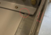
Before I remove metal and taper the edge to get the longeron to fit against the weldment, has anyone else run into this?

I can’t find anything in the instructions but it seems to be the only way to get it to fit.

The mothership was closed so I’m hoping someone has dealt with it.
 

Attachments

  • 74E5BE09-F18A-464C-98F3-1466ECC34B6C.jpg
    74E5BE09-F18A-464C-98F3-1466ECC34B6C.jpg
    214.9 KB · Views: 163
Webb,

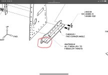
The area inside your red circle is to be removed from the angle F-802H-1 and F-802G-1. Looking closely at your picture, you can see faint dotted line stamped into the part to depict where it is supposed to be removed. The plans make it appear that this was to be done at the factory. Your parts must have skipped a processing step. I see that you have the angle riveted to the floor, so you will probably have to drill out those rivets to remove the part so you can cut the notch area out.

This notch allows the angle to clear the longeron and extend outboard, just on the side of the gear tower, with the longeron passing underneath it.

Once you do that, you will be able to slide the longeron farther inboard, closing up the gap to the weldment that you show with a gap with arrow.

See drawings 62 and 67.

Hope that helps
 
Last edited:
Before I remove metal and taper the edge to get the longeron to fit against the weldment, has anyone else run into this?

I can’t find anything in the instructions but it seems to be the only way to get it to fit.

The mothership was closed so I’m hoping someone has dealt with it.

A little unclear what you are talking about here, I'm looking at mine live and in person here, and that doesn't look like a weldament fitting but a part of the gear tower that should have been trimmed well before riveting. The pictured assembly definitely needs some serious remediation.
 
I feel your pain Webb. I made the same mistake. Steve explained it perfectly. I elected to remove the material in place with an 1/8” carbide burr and a Dremel tool. I put a strip of .010” steel under the angle to protect the floor and spent a day cutting away a few thousandths at a time to get it to clear. Not sure if it was worth it.
Good. Luck
 
Webb,

The area inside your red circle is to be removed from the angle F-802H-1 and F-802G-1. Looking closely at your picture, you can see faint dotted line stamped into the part to depict where it is supposed to be removed. The plans make it appear that this was to be done at the factory. Your parts must have skipped a processing step. I see that you have the angle riveted to the floor, so you will probably have to drill out those rivets to remove the part so you can cut the notch area out.

This notch allows the angle to clear the longeron and extend outboard, just on the side of the gear tower, with the longeron passing underneath it.

Once you do that, you will be able to slide the longeron farther inboard, closing up the gap to the weldment that you show with a gap with arrow.

See drawings 62 and 67.

Hope that helps

That make perfect sense. Easy enough to remove a few rivets and cut out the offending area now that I know. Sure would have been easier with it free in hand.

You sho do know how to make a fella cuss….

Thanks.
 
Last edited:
A little unclear what you are talking about here, I'm looking at mine live and in person here, and that doesn't look like a weldament fitting but a part of the gear tower that should have been trimmed well before riveting. The pictured assembly definitely needs some serious remediation.

It’s the gear tower angles. Mine wasn’t pre cut and I didn’t see any directions to cut on the dotted line.

I can see it on the drawing now that I’m specifically looking for it thanks to Steve. Definitely a Homer DOH moment.

It’s not a problem to take care of, just an inconvenience. Let’s just call this a plan gotcha and a side street on the road of my journey.

As a friend told me, the fastest way to build is to not have to do anything over.
 

Attachments

  • 6685606A-4E5C-49E9-9998-290BA70B82F7.jpg
    6685606A-4E5C-49E9-9998-290BA70B82F7.jpg
    119.9 KB · Views: 101
Last edited:
Another victim of the instructions!

I'm also on the list of guys who had this same error.

The directions could stand a revision as they don't call for the material removal, but the drawings do show it.

As stated in other posts, when you look close you will see the hatched markings on the piece.

I personally drilled out the rivets, removed the assembly, and trimmed it out with a Dremel and cutting wheel, smoothed the edges, and shot some more primer on it before reinstalling.

Everything fits like it should afterward. My lesson learned is in a match drilled kit things should fit. If it doesn't start to do some examination before setting rivets.

Best of luck and welcome to the club!

Shane
 
Chalk another one up!
Thats a total gotcha!
You can see it in the drawings now I’m looking for it. But it’s not mentioned anywhere, it’s not even mentioned on the drawing, they just look different!
 
Back
Top