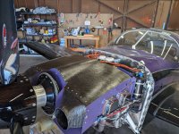
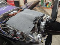
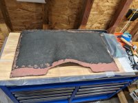
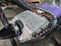
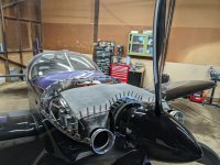
Original build was a Sam James long cowl with their plenum. It was slightly rushed to finish the plane, and I never liked the way it fit. I also didn't use enough fasteners and I think installed it way to low over the cylinders. Results were fine in cruise, 75% ROP would run around 400F, LOP would drop to 320-350 depending on OAT. Climbing out on hot days was done at 120-130 KIAS which limited the ceiling to about 11,000 ft at full gross. I had 2 weeks off while I'm changing jobs and decided to tackle rebuilding the plenum. I tore off all the old baffling and started with a new baffle kit from vans, modified for the ECI tapered cylinders. The plenum was created by vacuum bagging 3 layers of carbon to the inside of my cowl. I laid up pieces that were ~33 inches wide and 17" long. This wasn't enough depth, but was where the James cowl would allow for a mostly flat part between the oil door and where the round inlets started to become prominent. I then scarfed on 3" to the front to have enough depth to make all the connections. Once everything is fitted and riveted, I'll go back and add a 4th layer as an aesthetic top layer.
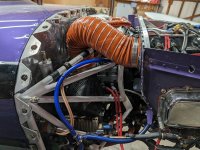
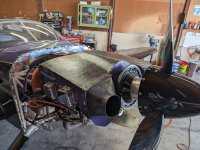
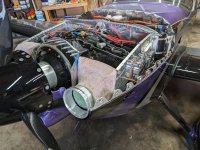
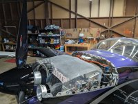
The new baffles got -4 piano hinge along the top and the carbon piece got -3. I cut up some random wing ribs to reuse the flanges. During final install, I'll tape one side up and form an in place gasket out of RTV to fully seal the piano hinge. The front piece has 5 holes per inlet nozzle for the top seal and 3 holes on each side of both inlets that will eventually get nut plates and a formed in place gasket. The hump over the top has a flange that will also get nut plates to hold it in place. Clearance between top of baffles and cowl was set at 3/4".
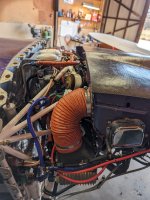
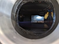
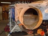
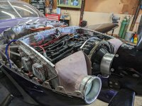
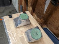
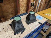
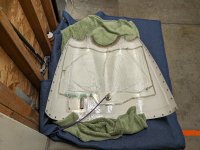
I carved the foam molds and wet laid 3 layers of carbon to form the round to square adapters. While carving. I used .065" spacers on each side of the molds to simulate the thickness of the carbon. This worked really well and it fit better than I expected.
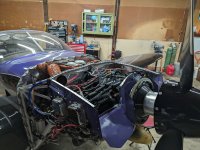
I've probably got just about 100-120 hours into this so far, and I still need to do the oil cooler line, fuel lines, and injector wire harness path throughs. I wanted to go 4" on the oil cooler line but just can't fit that around everything else under the cowl. I ordered some 3.5" sceet tubing today and should be able to make that work. I'm also waiting on nut plates and some more carbon for the new oil cooler shroud to arrive, plus I start my new job tomorrow, but will hopefully have an update and some finished pics in 2-3 weeks.
The new baffles got -4 piano hinge along the top and the carbon piece got -3. I cut up some random wing ribs to reuse the flanges. During final install, I'll tape one side up and form an in place gasket out of RTV to fully seal the piano hinge. The front piece has 5 holes per inlet nozzle for the top seal and 3 holes on each side of both inlets that will eventually get nut plates and a formed in place gasket. The hump over the top has a flange that will also get nut plates to hold it in place. Clearance between top of baffles and cowl was set at 3/4".
I carved the foam molds and wet laid 3 layers of carbon to form the round to square adapters. While carving. I used .065" spacers on each side of the molds to simulate the thickness of the carbon. This worked really well and it fit better than I expected.
I've probably got just about 100-120 hours into this so far, and I still need to do the oil cooler line, fuel lines, and injector wire harness path throughs. I wanted to go 4" on the oil cooler line but just can't fit that around everything else under the cowl. I ordered some 3.5" sceet tubing today and should be able to make that work. I'm also waiting on nut plates and some more carbon for the new oil cooler shroud to arrive, plus I start my new job tomorrow, but will hopefully have an update and some finished pics in 2-3 weeks.
Attachments
-
 PXL_20240216_015931720.jpg4.2 MB · Views: 247
 -
 PXL_20240217_060249221.jpg3 MB · Views: 204
 -
 PXL_20240217_212616224.jpg3.7 MB · Views: 200
 -
 PXL_20240217_212620167.jpg3.6 MB · Views: 200
 -
 PXL_20240217_215052813.jpg3.9 MB · Views: 203
 -
 PXL_20240218_011159979.jpg2.8 MB · Views: 202
 -
 PXL_20240218_031758967.jpg3.4 MB · Views: 196
 -
 PXL_20240219_013011943.jpg3.1 MB · Views: 193
 -
 PXL_20240219_013017741.jpg3.1 MB · Views: 194
 -
 PXL_20240209_044439834.jpg4 MB · Views: 251
Last edited: