

DrWalker
Member
Really enjoy the variety of amazing panels in this forum, but I'm stuck with the basics of how to attach the panel to the fuselage.
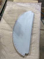
In the fuselage install manual and on drawings #27, it shows a 3/4" angle piece flat face against the front of the panel slightly above where the panel bends forward at the bottom. Side rails F-416 went on without difficulty and I see that the panel sits directly in front of the rails. However, the cutouts on each side seems to remove the portion of the panel that would attach to the 3/4" angle installed at the end of F-416. The plans show the bottom of the panel an inch or so lower than 3/4" angle which is on the opposite side of the panel.
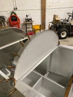
My initial read of the plans was to install the 3/4' angle across the entire panel and attach it to that, but that's doesn't look like all the panels I've seen and interferes with what little panel space is available and looks terrible (although it would be strong!) The overall width of the panel does not allow it to slide downward into the fuselage, but at it's lowest position the cutouts are adjacent to the 3/4" angle pieces that will be encased in the ends of F-416 and therefore does not provide material to attach it.
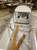
Since the instrument panel is the mounting for the F-421 upper fuselage cover and the canopy rests on this same arch, it clearly needs to have some ability to carry a load. What holds it up and how is attached? What is the distance from the longeron/F-416 side rails up to the top of the instrument panel?
In the fuselage install manual and on drawings #27, it shows a 3/4" angle piece flat face against the front of the panel slightly above where the panel bends forward at the bottom. Side rails F-416 went on without difficulty and I see that the panel sits directly in front of the rails. However, the cutouts on each side seems to remove the portion of the panel that would attach to the 3/4" angle installed at the end of F-416. The plans show the bottom of the panel an inch or so lower than 3/4" angle which is on the opposite side of the panel.
My initial read of the plans was to install the 3/4' angle across the entire panel and attach it to that, but that's doesn't look like all the panels I've seen and interferes with what little panel space is available and looks terrible (although it would be strong!) The overall width of the panel does not allow it to slide downward into the fuselage, but at it's lowest position the cutouts are adjacent to the 3/4" angle pieces that will be encased in the ends of F-416 and therefore does not provide material to attach it.
Since the instrument panel is the mounting for the F-421 upper fuselage cover and the canopy rests on this same arch, it clearly needs to have some ability to carry a load. What holds it up and how is attached? What is the distance from the longeron/F-416 side rails up to the top of the instrument panel?

")

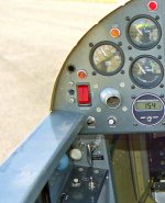
 I'll go look at it tomorrow. Comparing your picture to mine I can't quite tell what is going on with yours....

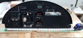
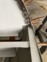
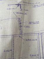
 The quickest way would be to form a patch to put in the corners (I assume both sides are screwed....I mean look the same...) to fill it in to the original plan design. SO: no on option #1, yes on option #2, IMHO. You can cut the patch out to match the plans before you flush rivet it on. This area is kind of tucked away under the supporting F-416 as seen in detail "C" in drawing 27 sp might not even show. Go look again the picture in post #9 of the port lower corner of my instrument panel. That is where this area is. Remembering that the supporting 6061-T6 'L' bracket (that rivets to F 416) is also riveted to the panel about where your new patch would be and that needs to be considered both in where your flush rivets are going to go and how it is riveted or bolted to the L bracket. In other words, the patch has to be made to avoid interfering with the supporting 6061-T6 L bracket from F-416. Does that make sense?

