What's new
Van's Air Force

Don't miss anything! Register now for full access to the definitive RV support community.

Another Honda 1.8L (NA) this time in an RV-9A

htx9a

Member
For anyone interested in following along, I'm working on my 9A in which I'll be installing a Honda 1.8L (aka Viking 150) with their "VIP" electric variable propeller and gearbox packages.

I'll say up front that I'm not retired and don't have a huge amount of spare time so who knows when this thing will fly, but building is half the fun of course.

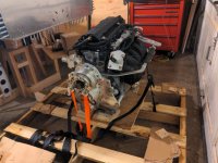
Here's the block as-delivered with the gearbox and prop pitch actuator attached.
2023-12-22-10-25-47-617.jpg


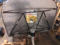
I went ahead and had Viking design a mount that incorporated the "new" elastomer gear leg and this is what they came up with. After reading through the mega-thread by @charosenz, I'd love any comments people have on it structurally. The tubing is 0.625" x 0.065" wall. (If anyone needs a stock Dynafocal I mount PM me...)
2023-12-28-09-33-44-004.jpg
 
Unfortunately I think I agree. I'm having my mech. engineer relative take a look. At minimum, I'd guess the nosegear upper pivot needs additional triangulation tying to the engine lower bar. Compared to similar mounts, it looks very shallow. I foresee some welding in my near future :rolleyes:
 
Mount

Unfortunately I think I agree. I'm having my mech. engineer relative take a look. At minimum, I'd guess the nosegear upper pivot needs additional triangulation tying to the engine lower bar. Compared to similar mounts, it looks very shallow. I foresee some welding in my near future :rolleyes:

It should be a simple task to model that mount in something like solid works where an FEA analysis could be conducted. That would give you more info…
 
Concerned about fore/aft motion of upper two engine mount bolts transfer to upper fuselage bolts.

A forward force on the two upper bolts (pulling positive Gs on prop/engine) will try to pull the two firewall bolts together (trying to buckle the firewall angle between them).

Triangulation for the upper two engine bolts looks really shallow. Any way they could be made to reach the firewall (angle)? But then I don't know how strong the angle behind the firewall is.

I'm not a mechanical engineer.Just trying to visualize the forces acting on the mount.

Finn
 
Best have a real ME evaluate that design. Looks very flimsy to put it mildly. Your life depends on this not folding up when G or propeller gyroscopic precession loads are applied.
 
Best have a real ME evaluate that design. Looks very flimsy to put it mildly. Your life depends on this not folding up when G or propeller gyroscopic precession loads are applied.

It's a 9A - shouldn't be any gyroscopic precession loads of high order like you would see in aerobatics - in theory.

In theory, there is no difference between theory and practice. In practice, there is considerable difference.
 
I think the issue here is that you have a rather narrow engine close to the firewall.

Fuselage is designed to take the engine load at its sides.

Don't know the RV-9A fuselage design and what's possible, but I suspect the best solution to the problem may be to add structure aft of the firewall.

As an example, the fore/aft motion of RV-3 and RV-4 landing gear required that attachment points near fuselage center be added. That in turn required that angles be added aft of the firewall reaching all the way back to the main wing spar.

Not saying that a structure has to reach all the way to the instrument panel, but there may be more space for additional engine mount structure behind the firewall than in front of it.

The RV-9A may not experience high Gs in flight, but how about a hard landing? That will force the engine downward, pulling on the two top bolts and pushing on the two bottom bolts of the engine. Those forces have to be transferred to the fuselage at the points the fuselage was designed for (the four corners of the firewall).

Edit: Think of it this way: A bridge can be supported by structure below it or above it or both.

Finn
 
Last edited:
Based entirely off of the limited info from the single picture, and assuming the mount is “complete” (no more tubes to add), then I would strongly suggest that you have this structure analyzed by an impartial and competent engineer. I see many red flags in the picture.
 
This was easier to model than I expected. Learning new tools is fun when you have a real application. I'll update when I have some FEA results.

frame1.jpg
 
Remember

This was easier to model than I expected. Learning new tools is fun when you have a real application. I'll update when I have some FEA results.

frame1.jpg

Remember, you need to account for acceleration loads, gyroscopic, and torsional loads when you model it. Think worst case scenario…
 
This was easier to model than I expected. Learning new tools is fun when you have a real application. I'll update when I have some FEA results.

frame1.jpg

Good start. Where is the fuselage structure in this?

Again (maybe I'm unable to make myself clear), you cannot consider the points where the mount attaches to the fuselage infinitely strong.

Finn
 
Brian welcome to experimental aviation.....

Brian,

Welcome to experimental aviation. I took your comment about my "mega" thread as a compliment. I think any thread that has over 300,000 views is not a reflection of me as much as it is that there is interest in the topic.

I am not qualified to comment on the Gear Leg you proposed. You will get some very good advice here, but be aware that many folks who offer opinions really have no experience at what they are commenting on.

An inflight adjustable pitch prop made a significant improvement on my cruise, but then again that was mostly taking advantage of the turbo.....I got close to 20mph increase in speed with my IFA IVO. I saw at least 174mph TAS at 10,000 feet at 34inches of manifold.

Good luck and enjoy the process. Feel free to contact me if you want. As you know, I did not have a Viking Engine, just their PSRU. I never had any issues with the PSRU other than I had to increase my cooling inlet to keep it cooled.

P.S. I am going to add a conclusion to my mega-thread to update what I have learned about the engine since the new owner crashed it.

Charlie Rosenzweig
 
Last edited:
Here are some initial results representing an upward gust at minimum aircraft mass generating a 4.9 load factor (0.5g more than the 4.4g load limit factor of the -9). A downward force of 5684N and thrust force of 886N are applied at the sphere representing the center of mass of the engine.

With a peak of 223 MPa = 32343 psi this still shows a safety factor of 2.06:1.

Note that the simplified rigid structure attached to the front of the mount has vertical members to represent the rigidness of the engine block. The conical isolators will have some deflection that should be accounted for. Without this vertical constraint, the bottom bar flexes and the bending moments fail the lower mount bar.

frame_FEA_case_4.jpg


TODO:
- simulate the other relevant cases of hard pull up/down at Va and Vno, upward gust, lateral load, pitch and yaw gyroscopic loading
- add the horizontal aluminum angle behind the firewall to the model to evaluate the bending stress from pulling on the upper two mounts. @FinnFlyer I see what you're saying here. If necessary, an upper horizontal tube tying the upper two mount tubes together would take care of this.
- simulate the nosegear loads...does anyone have numbers on the load limit on the nosegear, as in where it buckles? I guess I can model that complex tapering shape too :)
- have the sims replicated by my ME

@rvbuilder2002 / @mburch - yes

@charosenz - thanks for popping in! I'm planning to imitate something between rv6ejguy's and your interpretation of a ventral radiator duct. I'll also plan for a decently sized ram air blast inlet for the gearbox based on your observations, though won't have a turbo.
 
For anyone interested in following along, I'm working on my 9A in which I'll be installing a Honda 1.8L (aka Viking 150) with their "VIP" electric variable propeller and gearbox packages.

I'll say up front that I'm not retired and don't have a huge amount of spare time so who knows when this thing will fly, but building is half the fun of course.

Here's the block as-delivered with the gearbox and prop pitch actuator attached.
2023-12-22-10-25-47-617.jpg


I went ahead and had Viking design a mount that incorporated the "new" elastomer gear leg and this is what they came up with. After reading through the mega-thread by @charosenz, I'd love any comments people have on it structurally. The tubing is 0.625" x 0.065" wall. (If anyone needs a stock Dynafocal I mount PM me...)
2023-12-28-09-33-44-004.jpg

Adding the photo to the site - it would not show up in my browser for some reason.

2023-12-22-10-25-47-617.jpg
2023-12-28-09-33-44-004.jpg

BTW, you might want to hang onto that engine mount in case you change your mind on what engine to use.
 
Last edited:
“Here are some initial results representing an upward gust….”

Does this analysis simulate shear only at the engine mount bolt locations, or does it account for the weight of that long engine and prop hanging several feet forward? In my mind, the rocking of the block downward pulls the upper tubes away from the firewall, creating a significant tension and lateral shear at the longerons. Can the basic aircraft structure handle this new geometry? And that’s assuming the lower tubes can withstand the resulting column loads without crippling.
 
... In my mind, the rocking of the block downward pulls the upper tubes away from the firewall, creating a significant tension and lateral shear at the longerons. Can the basic aircraft structure handle this new geometry? ...

Look at the standard dynafocal engine mount. Obviously the fuselage mount hole/structure is designed for a pull forward (assuming new engine/prop weight is similar to standard engine/prop weight).

As you can see from the stress analysis, there is significant tension on the upper tubes putting more than design side loads on the upper two bolts/structure. That's because of the very shallow angle of those tubes to the firewall compared to the standard dynafocal mount. In other words, if you visualize the force vectors parallel and fore/aft to the firewall, you now have a much, much higher parallel force vector component. The alum angle behind the firewall may or may not be able to take the resulting compression without buckling. Typically one would handle that by thickening the "beam". But the lighter solution is to make it a zig-zag structure as you see in cranes, bridges and roof trusses:
_______
/\/\/\/\/\
----------

That's why I was asking about extending the upper engine bolts to the firewall (and maybe adding diagonals between them and the corners) and/or adding structure aft of the firewall. As you probably know from beam deflection formula, the height of the beam factors in at the fourth power. In other words doubling the height of a beam results in 16 times less deflection.

Adding a big diameter thin walled tube between the two upper bolts may or may not solve it, but adding a few diagonal tubes may. Adding (height) to the fore/aft alum flange behind the firewall and extending the upper engine bolts to the firewall may be another solution. It all depends on what space will be available fore and aft of the firewall. You don't want an engine mount structure that interferes with accessories and hoses, if avoidable.

Sorry, getting too wordy here.

Finn
 
Here are some initial results representing an upward gust at minimum aircraft mass generating a 4.9 load factor (0.5g more than the 4.4g load limit factor of the -9).

Noting that the limit load factor you state above is correct for the weight you analyzed, you're probably aware that the RV-9/9A is only stressed for Normal Category limit load factors at Van's structural design Gross Weight of 1750 pounds, but just in case:

Ref: https://www.vansaircraft.com/flying-an-rv/

"The design operational stress limit for the RV-9/9A is utility category (+4.4/-1.75 G) at less than 1600 pound gross weight and is standard category (+3.8/-1.5 G) between 1600 pounds and the aircraft’s design gross weight.


Good luck with your build!
 
Last edited:
@charosenz - thanks for popping in! I'm planning to imitate something between rv6ejguy's and your interpretation of a ventral radiator duct. I'll also plan for a decently sized ram air blast inlet for the gearbox based on your observations, though won't have a turbo.[/QUOTE]

Brian,

Ross' cooling system design is considerably more efficient than what I built. But I was very happy with how mine turned out and performed. The last iteration that added a secondary inlet scoop proved very beneficial. I cannot remember how much I posted on that mod. Good luck and have fun.
 
I ran through all of the FEA cases and my ME relative got similar results with a different FEA program. The design appears to have a minimum of 1.7:1 factor of safety for engine-induced flight loads. Also, the landing gear strut forces begin to fail the mount at just over 3x the static maximum nose weight of 325 lbs. It's hard to compare without numbers for the stock mount, but I'll deem that acceptable for now.
frame_FEA_case_4_rev2.jpg


Although the mount can handle the loads, it's difficult to analyze buckling due to the inward compression loads on the firewall without modeling the whole upper firewall and longeron/weldment. It might be strong enough, but for an extra 3 pounds I can add an internal support like Finn is suggesting. This increases the safety factor to 2.65 for engine-induced flight loads and nearly zeros out the inward compression. Adding a center hole requires some reinforcement because it punches through the aluminum angle.
frame_FEA_case_4_rev2_internal.jpg
 
I weighed the engine and got about what I expected.
255 lbs including:
  • starter
  • alternator
  • wiring harness, sensors
  • CS prop actuator parts
Not including:
  • oil, coolant, hoses
  • propeller (9.7 lbs)
  • spinner (3 lbs)
  • exhaust (3.4 lbs)

2024-01-05-20-11-07-114.jpg
 
Last edited:
Another reason to do your own research and evaluation and question EVERYTHING. Viking is now advising to remove the catalyst material. They have recently switched to a new lightweight SS muffler design to replace the modified Honda OEM CC.

Current Viking 130 Service Bulletins:
EXHAUST BAFFLE
The exhaust system on the left was used on the Viking 130 until 2023. The exhaust on the right was used thereafter and is current. The earlier exhaust used a ceramic honeycomb baffle insert for muffling. Overtime this can deteriorate and must no longer be used.

Viking can remove this and install a metal baffle to adhere to the service bulletin. Alternatively, the later style can also be installed.


John Salak
RV-12 N896HS
 
I ran through all of the FEA cases and my ME relative got similar results with a different FEA program. The design appears to have a minimum of 1.7:1 factor of safety for engine-induced flight loads. Also, the landing gear strut forces begin to fail the mount at just over 3x the static maximum nose weight of 325 lbs. It's hard to compare without numbers for the stock mount, but I'll deem that acceptable for now.
frame_FEA_case_4_rev2.jpg


Although the mount can handle the loads, it's difficult to analyze buckling due to the inward compression loads on the firewall without modeling the whole upper firewall and longeron/weldment. It might be strong enough, but for an extra 3 pounds I can add an internal support like Finn is suggesting. This increases the safety factor to 2.65 for engine-induced flight loads and nearly zeros out the inward compression. Adding a center hole requires some reinforcement because it punches through the aluminum angle.
frame_FEA_case_4_rev2_internal.jpg


Shouldn’t you look at 4.4 G loading, then factor 1.5 or so over that. 1.7 factor total seems a little light being that a 60 degree turn is 2 Gs..
 
The effects of leaded fuel on catalytic converters has been known for decades (50+ years?). Did the supplier (notice I didn't say OEM) not deliver operating instructions warning against the use of leaded fuel? Unfortunately, I would not be surprised by any answer.
 
Aye, having a frangible ceramic in the exhaust path seems like a bad idea unless it's far from engine vibrations. It's unclear if this was also a catalytic converter of sorts. The exhaust I have is the newer version.

Thanks for the heads-up.

You can bet I'll be squinting at every component and considering failure modes.

(p.s. please make a new thread and link if everyone wants to comment on the crash)
 
Have you seen this one?

https://generalaviationnews.com/202...-converter-brings-down-experimental-airplane/

(And the remark of Viking that an engine needs back pressure in order to operate, or it will lose power???? One would think that there are enough episodes of Myth Busters and Engine Masters out there to debunk that old wives tale....)

Most engine designers understand what kind of flow and therefore back pressure will exist in the exhaust system and design around those parameters. If you up the flow rate and therefore reduce the back pressure, then yes, power level could likely go down; Fuel efficiency even more so. Same is true if you design for less back pressure then add more. There is a lot of science that goes into when to open and close valves to optimize scavenging in the overlap period. If you are using stock Honda cams with stock cam timing, you should strive to keep exhaust flow similar to the system used for that engine. Exh header design (i.e. tube length before collector) is also a factor here. Some designers use neighboring exh low pressure points in their design to help with scavenging.
 
Last edited:
Shouldn’t you look at 4.4 G loading, then factor 1.5 or so over that. 1.7 factor total seems a little light being that a 60 degree turn is 2 Gs..

The 1.7 factor is considering a 4.9g loading, so yield at ~8.3g. Something else important will break first.
 
Back
Top