Tall_Order

Well Known Member
Patron
I have a single sheilded and grounded wire supplying external audio(EFIS, GPS, Media, etc) to my radio/intercom. Source is the Audio out of an AP-60. Everything sounds great as long as there is some source of active audio. Otherwise there is a very mild hiss when it should be silent and I've flown airplanes with worse- I'm just trying to get it as close to perfect if I can. My radio also can place a negative dB on that input but it is still mildly perceptible.

The thing is if I turn this input off, the headphone is perfectly silent other than intercom/radio. The aux input is at line level so I understand we are working around the 1V range. I tried pulldowns but anything over 1 ohm allows the hiss(and is way to aggressive to pass media without distortion). I am thinking of maybe a small zener diode to try activate a signal relay but there might be a better way. Ideally if there is just a 1.5" sparkfun PCB module or such. Ferrite chokes in various positions don't seem to have an effect either. Anybody aware of other strategies?
 
In audio installations - Single point grounding is very important. Use differential signals if available (ie: audio out+ & audio out-) within a shielded cable (only ground shield at ONE end). When only a single ended signal is being used (ie: audio out) then run it within a shielded cable (only grounded at ONE end).
Without a somewhat detailed schematic of what your actual installation is - that the best advise I can share.
Luckily when I bought this intercom/radio setup, it came with a professionally made wiring bundle so that part is done :)

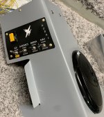
Messing with it some more, it appears that the problem was that I had 3 of the 6 headphone AP-60s input wires floating(disconnected because I'm in the midst of final wiring things now), and when I grounded them, the hiss is almost completely gone. However, I'm not homefree yet as if I turn on my interior lighting LED controllers while having this AUX audio wire enabled on my intercom, there is audio noise regardless of where on the airframe I ground the LED circuit... I included a picture of my DIY audio panel that runs twin AP-60s, one for speaker and one for phone so you can see how everything gets funneled into one wire.


To clarify the question I was wondering if anyone knew of an off-the shelf PCB module or simple circuit that would only pass a mono audio signal when volume above a certain threshold. Even if there is a sensor that would detect audio and give me a true/false, I can figure the rest out. Ideally just ground this wire if the input is at a whisper or below.
 

Attachments

  • AudioPanel.JPG
    AudioPanel.JPG
    146.2 KB · Views: 25
Luckily when I bought this intercom/radio setup, it came with a professionally made wiring bundle so that part is done :)

Messing with it some more, it appears that the problem was that I had 3 of the 6 headphone AP-60s input wires floating(disconnected because I'm in the midst of final wiring things now), and when I grounded them, the hiss is almost completely gone. However, I'm not homefree yet as if I turn on my interior lighting LED controllers while having this AUX audio wire enabled on my intercom, there is audio noise regardless of where on the airframe I ground the LED circuit... I included a picture of my DIY audio panel that runs twin AP-60s, one for speaker and one for phone so you can see how everything gets funneled into one wire.


To clarify the question I was wondering if anyone knew of an off-the shelf PCB module or simple circuit that would only pass a mono audio signal when volume above a certain threshold. Even if there is a sensor that would detect audio and give me a true/false, I can figure the rest out. Ideally just ground this wire if the input is at a whisper or below.
It sounds like you may have a LED dimmer circuit based on switching or chopper technology as opposed to a linear regulator - switching dimmers, like switching power supplies are more efficient than linear technologies however they do create noise....some is radiated but most is "conducted" on power lines. I think that carefully reviewing your power sourcing to the audio equipment, not just grounding, may yield benefits. Think in terms of single point audio power to all audio equipment which is tied to your power bus nearest your battery (batteries are great filters). If you want to short the input when no audio is present - that sounds like a squelch type function - maybe search for that type of Ckt... or design your own using a couple FET transistors & a potentiometer to set desired level. The Ham Radio Handbooks are good sources of designs and ideas for that stuff.
Nice Picture.
 
First the LED noise. Some inexpensive LEDs use a pulse width modulated (‘PWM’) driver e.g., on for a millisec, off for 10 msec, on for 1 msec, …. To keep from overheating the LEDs. These are very efficient but that PWM signal tends to radiate RF noise, and that takes a lot of careful shielding to eliminate. My advice: ditch the PWM power supply, go to a adjustable dc supply with dropping resistors. You’ll use more electrical power, but no noise.
If you want a schematic of a threshold detector, copy the squelch circuit from an intercom. I built my own, can send the schematic via email if you want. (PM me your email). It’ll take a few days for me to dig it out.
 
Thanks for the input gents, perhaps I learned the hard way now about the PWM/EMI relationship... Not until I got to Audio and reading here that I discovered that this was even an issue 😕 It is on its own VP-X pin but appears that may not be sufficient isolation.

Ideally, I'd like to just tear out the controllers and not the painstakingly installed LED strips (2 circuits: panel and flood). Looking at the pair of 555 chips on the (credit card sized) controllers I would say it's a safe bet it's PWM. The LEDs are 12V strips. Any recommendations for a potentiometer as a rheostat vs a voltage divider+resistor or is there a better practice for the circuit architecture? Even with more inefficiency, I'm thinking each circuit would be under 25W but can confirm with the VPX once rewired. Better yet, if there is an off-the shelf PCB module you are aware of for this?
I like the 2 channel device described in the attachment, think they are sourced from Stein.
 

Attachments

  • TCVR-2 Panel Dimmers.pdf
    2 MB · Views: 15
Any recommendations for a potentiometer as a rheostat vs a voltage divider+resistor or is there a better practice for the circuit architecture? Even with more inefficiency, I'm thinking each circuit would be under 25W but can confirm with the VPX once rewired. Better yet, if there is an off-the shelf PCB module you are aware of for this?
A wire wound rheostat would work, but they’re heavy, expensive, get hot. Use a cheap potentiometer to control a cheap LM317 voltage regulator. Each LED should have its own series current limiting resistor so this involves considerable re-work. If you’re coming close to the 1.5 A current limit for the LM317 you should heat sink it. I use one of these to control a string of LEDs under the glare shield; the other controls the internal illumination of avionics.
 
Thanks for the input gents, perhaps I learned the hard way now about the PWM/EMI relationship... Not until I got to Audio and reading here that I discovered that this was even an issue 😕 It is on its own VP-X pin but appears that may not be sufficient isolation.

Ideally, I'd like to just tear out the controllers and not the painstakingly installed LED strips (2 circuits: panel and flood). Looking at the pair of 555 chips on the (credit card sized) controllers I would say it's a safe bet it's PWM. The LEDs are 12V strips. Any recommendations for a potentiometer as a rheostat vs a voltage divider+resistor or is there a better practice for the circuit architecture? Even with more inefficiency, I'm thinking each circuit would be under 25W but can confirm with the VPX once rewired. Better yet, if there is an off-the shelf PCB module you are aware of for this?

these work well:
 
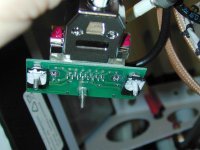
The TCVR-2 Panel Dimmer DOES get heat sunk to mounting surface - see attached install pictures. Your plane makes a GREAT heatsink with no extra weight.
 

Attachments

  • DSCE3899.JPG
    DSCE3899.JPG
    109.8 KB · Views: 8
  • DSCE3898.JPG
    DSCE3898.JPG
    82.6 KB · Views: 8
Thanks for the leads on the components! I live north of the 49th, which means shipping for any parcel is often north of $49 too 🙃

So for bang for the buck I might give a couple of this type a try as an experiment. I'll desolder the trim potentiometer and replace with a real one and see how it works out.