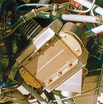
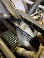
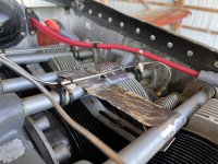
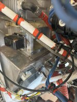
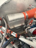
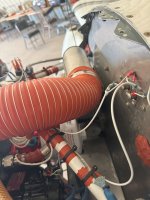
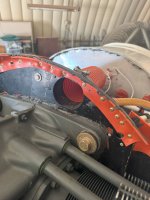
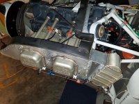
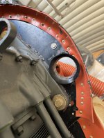
I'm looking to further optimize my oil cooler setup, in a ROP cruise I'm seeing temperatures between 210-220 *F at OATs of around 40*; CHTs in this cruise regime are 380-390*; my engine is a parallel valve 320 with piston squirters. My cooler is a 7 row Aero Classic (PN 8000075) supplied by -8 hoses, mounted on the firewall and fed by a 3" SCAT run from the rear baffle above the left side of the case. The cable actuated door under the cooler exhaust vents to the cabin for a form of marginal cabin heat. As the attached photos show, this is a decidedly non-standard mounting solution. The cooler is getting oil and air, easily proven by moving the door to vent the cooler to the cabin rather than the lower plenum, and seeing the oil temperature increase rapidly. Placing my hand by the vent tells me the cooler is warm, although there isn't much air going through it. Of note, cylinder #4 is typically my coldest cylinder.
Any input as to potential solutions here that could make this setup workable are welcome. I'm so far leaning towards 3D printing a bell mouth for the inlet and maybe a better transition piece for the cooler face. Moving to a 4" SCAT would be tricky with how the baffling is trimmed, and would need to be off #4 most likely, as there isn't sufficient room where the existing 3" duct flange is.
Any input as to potential solutions here that could make this setup workable are welcome. I'm so far leaning towards 3D printing a bell mouth for the inlet and maybe a better transition piece for the cooler face. Moving to a 4" SCAT would be tricky with how the baffling is trimmed, and would need to be off #4 most likely, as there isn't sufficient room where the existing 3" duct flange is.
")


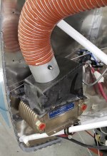


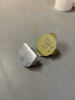
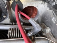
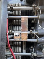
 Exit gate cable-controlled from the cockpit; it's usually closed. I have to block off most of the intake, especially in the Winter as the oil is always on the cool side of the gauge. The third picture is of the sophisticated intake blocking mechanisms. The upper is for cold weather, the lower for warmer weather. PS: since these pictures were taken, the nuts have been replaced with steel locknuts. CHT on that cylinder: consistently in the 280-300 range, cruise; 350-370 extended climb.